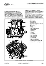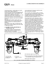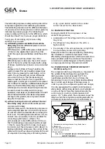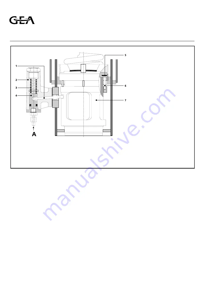
and lift the suction valve ring. Shortly after the
compressor has been started, control oil pressure
is admitted to the piston and moves it upward, so
that the lever tilts, thus pulling the lifting bush
with the push pins downwards while the suction
valve ring descents onto its seat. After completion
of the latter movement, the cylinder is in
operation.
4.6 CYLINDER HEAD COOLING
All cylinder heads on the compressor are provided
with a cooling water jacket and blanked off water
in- and outlet connections.
Only in cases where extremely high cylinder head
temperatures occur, will this possibility of cylinder
head cooling be used by the installation engineer.
In these cases reference is made to the details
given in the plant manual.
4.7 PRINCIPAL CONNECTIONS AND SUCTION
GAS STRAINER
The suction and discharge chambers of the
cylinders open, via one or more lines, into a single
suction and discharge connection with flange,
with which the compressor is coupled to the
refrigerating plant via stop valves. The (LP)-suction
connection is fitted on the suction strainer
housing, in which a removable metal strainer
element is provided for purifying the intake
refrigerant gas. Compressor type RC69 is provided
with two strainer elements.
In the case of two-stage compressors, the
LP-discharge connection is connected, via an
interstage cooler, to the HP-suction connection
(see also Chapter 5, par. 5.6, Injection interstage
gas cooler). Compressor type RC429 includes
already a built-in HP-suction strainer.
All principal connections have nipples for
connecting pressure gauges or pressure safety
switches.
4.8 PRESSURE EQUALIZING LINE AND
OVERFLOW SAFETY VALVES
Between suction strainer housing and crankcase
an equalizing line is provided in order to prevent
the crankcase pressure* from rising due to piston
leakage. Moreover, the crankcase can thus be
evacuated for charging lubricating oil or for
venting the compressor.
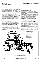
FIG. 4.4 VALVE—LIFTING MECHANISM
1. Lever
2. Piston housing
3. Spring
4. Control piston
5. Suction valve ring
6. Push pin
7. Lifting bush
A
Control oil pressure
Refrigeration Division
Grasso
4. GENERAL DESCRIPTION THE COMPRESSOR
Page 4.4
Refrigeration Compressors Series RC9
v002.97.10.en

