After starting the compressor, the through-flow of
the control oil pressure to the valve lifting
mechanisms is interrupted for 30 to 60 seconds by
a hydraulic delay valve provided in the pump. This
valve consists of a plunger and a spring-loaded
piston. During compressor standstill the piston,
due to the spring tension, is in its extreme
position, as a result of which the plunger shuts off
the through-flow of oil. The space behind the
piston is filled with oil. As soon as the compressor
is operated, plunger and piston will be forced
down by the pump pressure, but encounter
resistance of the oil behind the piston. This oil
should first leak away along the piston before the
plunger can clear the through-flow.
The delay time depends on the viscosity and
consequently on the oil temperature. As soon as
the compressor has stopped, it may not be
restarted until after 3 minutes in order to prevent
the compressor from starting on load. During this
period the delay valve is returned by the spring to
its original position. A check valve in the piston
ensures that the space behind the piston is filled
again with oil.
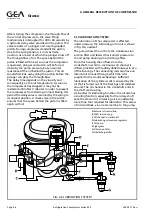
4.10 LUBRICATION SYSTEM
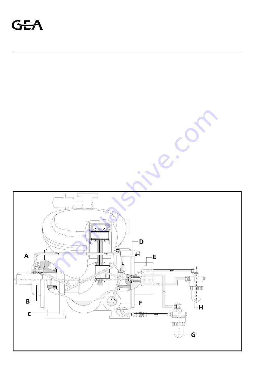
The lubrication of the compressor is effected
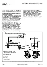
under pressure; the lubricating oil circuit is shown
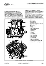
in fig. 4.6, overleaf
The pump draws the oil from the crankcase via a
suction filter and feeds it back under pressure to
the oil pump housing via a discharge filter.
From this housing the oil flows into the
crankshaft, in which a continuous oil channel is
drilled, provided with radially drilled oilways in situ
of the bearings. The connecting rods also have an
internal oil channel through which the oil is
supplied to the small end bearings. Sufficient
lubrication of the cylinder walls is ensured by the
oil that is forced out of the bearings and splashed
around. The oil channel in the crankshaft ends in
the shaft seal housing.
As, besides its lubricating function, the oil also has
a cooling function, especially for the rotary shaft
seal, the amount of circulating oil is considerably
more than that required for lubricaton. This excess
of oil is led back, via an external line to the pump
FIG. 4.6 LUBRICATION SYSTEM
A
External oil return line
B
Shaft seal housing
C
Oil channel in crankshaft
D
Lubricating oil pressure regulator
E
Oil pump
F
Sight glass
G
Oil suction filter
H
Oil discharge filter
Refrigeration Division
Grasso
4. GENERAL DESCRIPTION THE COMPRESSOR
Page 4.6
Refrigeration Compressors Series RC9
v002.97.10.en

