background image

 D
 GB
 F
 E
 I
 Ru

25

09791-01.2015-DGbFEIRu

1

2

3

4

5

6

7

8

9

10

11

12

13

Schmierung / Ölkontrolle

 Bei Inbetriebnahme Öldruckkontrolle mittels Manometer über 

den Schraderanschluss an der Ölpumpe vornehmen.

  Nach Erreichen des Beharrungszustands (kontinuierliche 

Betriebsbedingung) Ölstand des Verdichters kontrollieren. 

Er soll im Schauglasbereich sichtbar sein (siehe Bild).

  Automatische Überwachung durch Öldifferenzdruckschalter. 

Bei Inbetriebnahme Funktionsprüfung des Öldifferenzdruck-

schalters vornehmen.


Bei Abschaltung durch das Gerät ist eine Störanalyse vorzunehmen.

Hinweise auf dem Deckel des Schalters beachten.
WARNUNG! Wenn größere Ölmengen nachgefüllt werden müssen, besteht die Gefahr von 

Ölschlägen. In diesem Falle muss die Ölrückführung überprüft werden.

i

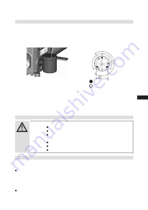
Anschluss Ölspiegelregulator

Bei Verbundschaltungen von mehreren Verdichtern haben sich 

Ölstandsregulierungssysteme bewährt. Für die Montage eines Ölspie-

gelregulators ist der Anschluss „O“ vorgesehen (siehe Maßzeichnung). 

Alle gängigen Ölspiegelregulatoren von AC&R, ESK sowie das elek-

tronische Reglersystem TRAXOIL S1A1 von SPORLAN können direkt 

ohne Adapter angeschlossen werden (s. Abb.). Ein Schauglas am 

Ölspiegelregulator ist nicht erforderlich.

124 o

124

o

124

o

124

o

47,6

M6 x 10

je 3 mal

3-Loch-Anschlussbild für ESK

,


AC&R

 und CARLY

3-Loch-Anschlussbild für TraxOil

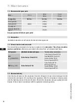
7.1 Preparation

7.2  Work to be carried out

7

|

 Maintenance

In order to guarantee optimum operational reliability and service life of the compressor, 

we   recommend 

carrying out servicing and inspection work at regular intervals:


Oil change: 

   - 

not mandatory for factory-produced series systems.

   - 

 for field installations or when operating near the application limit: for the first time after 100 

to 200 operating hours, then approx. every 3 years or 10,000 - 12,000 operating hours. 
Dispose of used oil according to the regulations; observe national regulations.


Annual  checks:

 Oil level, leak tightness, running noises, pressures, temperatures, function of 

 auxiliary devices such as oil sump heater, pressure switch.

WARNING!  Before starting any work on the compressor:


 Switch off the compressor and secure it to prevent a restart.


 Relieve compressor of system pressure.


 Prevent air from infiltrating the system!


After maintenance has been performed:


 Connect safety switch.


 Evacuate compressor.


 Release switch-on lock.

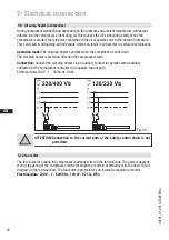
6.8  Connection of oil level regulator

Oil level regulation systems have proven themselves with parallel circuits of several compressors. 
The connection "0" is provided for installing an oil level regulator (see dimensions drawing). All 
common oil level regulators from AC&R, ESK and Carly as well as the OM3 TraxOil oil level regulation 
system from Alco can be connected directly without adapters (see Fig. 19). A sight glass on the oil 

level regulator is not required.

Mechanical oil level regulator
at the "O" connection

Fig. 21

6

|

 Commissioning

3 times each

3 hole connection diagramm for
ESK, AC&R and CARLY
3 hole diagramm for TraxOil

Summary of Contents for HA4

Page 1: ...2015 DGbFEIRu engineering for a better world GEA Bock Compressor HA4 Assembly instructions HA4 310 4 HAX4 310 4 HA4 385 4 HAX4 385 4 HA4 465 4 HAX4 465 4 HA4 555 4 HAX4 555 4 HA4 650 4 HAX4 650 4 1 2...

Page 2: ...he compressor can result in serious or fatal injury Observe the safety instructions contained in these instructions These instructions must be passed onto the end customer along with the unit in which...

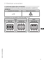
Page 3: ...or design for direct or part winding start 5 3 Basic circuit diagram for part winding start with standard motor 5 4 Special motor design for direct or star delta start 5 5 Basic circuit diagram for st...

Page 4: ...potential dangers WARNING Refrigerating compressors are pressurised machines and therefore require particular caution and care in handling Risk of burns Depending on the operating conditions surface t...

Page 5: ...ck refrigerating compressor named in the title is intended for installing in a machine within the EU according to the EU Directives 2006 42 EC Machinery Directive 97 23 EC Pressure Equipment Directive...

Page 6: ...drive motor on the compressor case Specially or deep cooling with air cooled motor and direct suction at the cylinder Name plate Fig 1 2 1 Brief description Oil sight glass Valve plate Cylinder cover...

Page 7: ...splacement 4 Starting current rotor blocked 9 Voltage circuit frequency Y Part winding 1 10 Nominal rotation speed YY Part windings 1 and 2 11 Displacement 5 ND LP max admissible operating pressure 12...

Page 8: ...In the case of operation above the mains frequency the application limit can therefore be limited When operating in the vacuum range there is a danger of air entering on the suction side This can cau...

Page 9: ...temperature Evaporation temperature C Condensing temperature C Suction gas superheat K Suction gas temperature C Fig 5 Fig 4 3 Areas of application R404A R507 R22 Design for other areas on request Ma...

Page 10: ...e adequate compressor ventilation The compressor must not be in the air stream to another component of the refrigeration system e g condenser The cooling of the drive motor must be reliable guaranteed...

Page 11: ...yers of rust and phosphate Only use air tight parts Lay pipes correctly Suitable vibration compensators must be provided to prevent pipes being cracked and broken by severe vibrations Ensure a proper...

Page 12: ...onnections Fig 15 Opening the shut off valve Spindle turn to the left counter clockwise as far as it will go Shut off valve completely opened service connection closed The connection which cannot be s...

Page 13: ...ct or partial winding start The motor winding is subdivided into two parts Partial winding 1 66 and part winding 2 33 This winding division reduces the start up current needed for a part winding start...

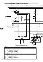
Page 14: ...monitor F4 Safety chain high low pressure monitoring F5 Oil differential pressure monitor C1 Fan operating capacitor B1 Release switch thermostat Fig 17 nderung 0 Datum Name Datum Bearb Gepr Norm 1 02...

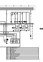
Page 15: ...or part winding 1 K2 Mains contactor part winding 2 K1T Delay relay max 1s S1 Control voltage switch E1 Oil sump heater PW MP10 5 6 7 BOCK COMPRESSORS 8 9 Bl 1 Bl 1 M 1 M1 1 K1 9 X3 1 10 2 C1 3 F5 4 T...

Page 16: ...do this results in opposed rotary fields and results in damage to the motor After the motor starts up via partial winding 1 partial winding 2 must be switched on after a maximum delay of one second F...

Page 17: ...1 W1 U1 V2 U2 W2 L3 L2 L1 400 V Y nur Direktstart V1 W1 U1 V2 U2 W2 L1 L2 L3 5 4 Sondermotor Ausf hrung f r Direkt oder Stern Dreieck Anlauf F r den Stern Dreieck Anlauf ist eine mechanische Anlaufent...

Page 18: ...hain high low pressure monitoring F5 Oil differential pressure monitor C1 Fan operating capacitor B1 Enabling switch thermostat Q1 Main switch nderung 0 Datum Name Datum Bearb Gepr Norm 1 20 Feb 2009...

Page 19: ...relay S D changeover K5T Delay relay start unloader S1 Control voltage switch AL Start unloader E1 Oil sump heater D S MP10 5 6 7 BOCK COMPRESSORS 8 9 Bl 1 Bl 1 9 X3 1 M 1 M1 1 10 2 K1 11 3 C1 4 F5 K1...

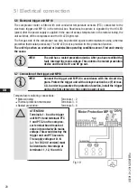
Page 20: ...he compressor and the H1 LED lights red The hot gas side of the compressor can also be protected against overtemperature using a thermal protection thermostat accessory The H2 LED red is provided for...

Page 21: ...connection 1 or 2 Release the hot gas temperature sensor if installed 3 or 4 2 Restore the power supply L1 or S1 ON Function check of motor temperature sensor operational ON Function check of hot gas...

Page 22: ...ll and depending on the pressure and ambient temperature refrigerant diffuses into the compressor s lubricating oil This reduces the oil s lubricating ability When the compressor is started the refrig...

Page 23: ...allation side The compressor has undergone trials in the factory and all functions have been tested There are therefore no special running in instructions Check the compressor for transport damage 6 2...

Page 24: ...open before starting the compressor Check that the safety and protection devices pressure switch motor protection electrical con tact protection measures etc are functioning properly Switch on the co...

Page 25: ...operating hours then approx every 3 years or 10 000 12 000 operating hours Dispose of used oil according to the regulations observe national regulations Annual checks Oil level leak tightness running...

Page 26: ...late This oil type should be used as a preference Alternatives are stated in the extract from our lubricants table below Refrigerants GEA Bock standard oil types Recommended alternatives HFC e g R404A...

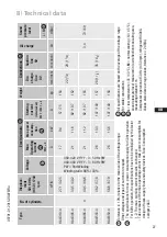
Page 27: ...V Y YY 3 60 Hz PW PW Part Winding Winding ratio 66 33 L M 5 Tolerance 10 relative to the mean value of the voltage range Other voltages and types of current on request The specifications for max power...

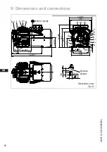
Page 28: ...ldrucksicherheitsschalter OIL Connection oil pressure safety switch OIL Raccord pressostat de s curit d hu D Anschlu ldrucksicherheitsschalter LP Connection oil pressure safety switch LP Raccord pres...

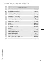
Page 29: ...ssure switch OIL 7 16 UNF D Connection oil pressure switch LP 7 16 UNF D1 Connection oil return from oil separator 1 4 NPTF E Connection oil pressure gauge 7 16 UNF F Oil drain M22 x 1 5 H Oil charge...

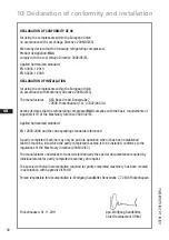
Page 30: ...pressor HA4 complies with the basic requirements of Appendix II 1B of the Machinery Directive 2006 42 EC Applied harmonised standard EN 12693 2008 and the corresponding standards referenced A partly c...

Page 31: ...estions about installation operation and accessories please contact our techni cal service or specialist wholesaler and or our representative The GEA Bock service team can be contacted by phone with a...

Page 32: ...9454 137 refrigeration gea com www gea com We live our values Excellence Passion Integrity Responsibility GEA versity GEA Group is a global engineering company with multi billion euro sales and operat...

Reviews: