background image

20

 D
 GB
 F
 E
 I
 Ru

09958-12.2014-DGbFEIRu

5

|

 Electrical connection   

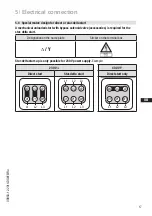
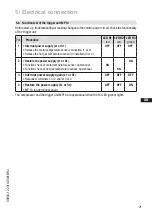
ATTENTION! 
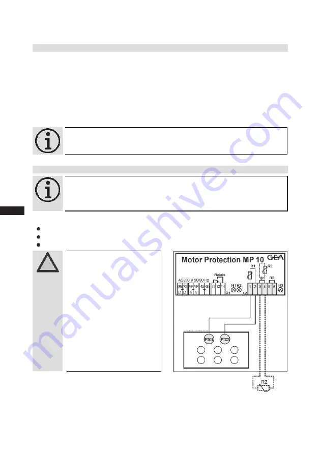
Terminals 1 - 6 on the trigger 
unit MP 10 and terminals PTC 
1 and PTC 2 on the compres-
sor terminal board must not 
come into contact with mains 
voltage. This would destroy the 
trigger unit and PTC sensors.
The supply voltage at L1-N 
(+/- for DC 24 V version) must 
be identical to the voltage at 

terminals 11, 12, 14 and 43. 

5.6  Electronic trigger unit MP 10

The  compressor  motor  is  fitted  with  cold  conductor  temperature  sensors  (PTC)  connected  to  the 

electronic trigger unit MP 10 in the terminal box. Readiness to operate is signalled by the H3 LED 
(green) after the power supply is applied. In the case of excess temperature in the motor winding, the 
unit switches off the compressor and the H1 LED lights red.
The hot gas side of the compressor can also be protected against overtemperature using a thermal 
protection thermostat (accessory). The H2 LED (red) is provided for the protection function.

The unit trips when an overload or inadmissible operating conditions occur. Find and remedy 
the cause.

5.7  Connection of the trigger unit MP10

INFO!  

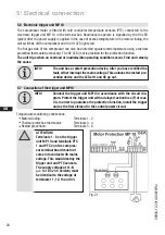
Connect the trigger unit MP10 in accordance with the circuit dia-
gram. Protect the trigger unit with a delayed-action fuse (F) of max. 

4 A. In order to guarantee the protection function, install the trigger 
unit as the first element in the control power circuit.

Temperature monitoring connections:

 Motor winding: 


Terminals 1 - 2

 Thermal protection thermostat: 

Terminals 3 - 4

 Restart prevention:   


Terminals 5 - 6

INFO!  

The unit has a restart prevention device. After you have rectified the 
fault, either interrupt the mains voltage. This unlocks the restart pre

-

vention device and the LEDs H1 and H2 go out.

Terminal board

Fig. 21

Summary of Contents for HG4/310-4

Page 1: ...A Bock Compressor HG4 Assembly instructions HG4 310 4 HG4 310 4 S HGX4 310 4 HGX4 310 4 S HG4 385 4 HG4 385 4 S HGX4 385 4 HGX4 385 4 S HG4 465 4 HG4 465 4 S HGX4 465 4 HGX4 465 4 S HG4 555 4 HG4 555...

Page 2: ...he compressor can result in serious or fatal injury Observe the safety instructions contained in these instructions These instructions must be passed onto the end customer along with the unit in which...

Page 3: ...dard motor design for direct or part winding start 5 3 Basic circuit diagram for part winding start with standard motor 5 4 Special motor design for direct or star delta start 5 5 Basic circuit diagra...

Page 4: ...potential dangers WARNING Refrigerating compressors are pressurised machines and therefore require particular caution and care in handling Risk of burns Depending on the operating conditions surface t...

Page 5: ...ck refrigerating compressor named in the title is intended for installing in a machine within the EU according to the EU Directives 2006 42 EC Machinery Directive 97 23 EC Pressure Equipment Directive...

Page 6: ...or Flange mounted drive motor on the compressor case Preferred application range normal refrigerating and air conditioning 2 1 Short description Dimension and connection values can be found in Chapter...

Page 7: ...ge circuit frequency 2 Machine number 7 Nominal rotation speed 3 maximum operating current 8 Displacement 4 Starting current rotor blocked 9 Voltage circuit frequency Y Part winding 1 10 Nominal rotat...

Page 8: ...um current and power consumption must not be exceeded In the case of operation above the mains frequency the application limit can therefore be limited When operating in the vacuum range there is a da...

Page 9: ...ation Design for other areas on request R134a R407C R404A R507 R22 Fig 4 Fig 5 Fig 6 Fig 7 Unlimited application range Supplementary cooling or reduced suction gas temperature Supplementary cooling an...

Page 10: ...ng inert gas to inhibit oxidation products scale 4 3 Pipe connections F E D C 1 2 3 INFO New compressors are factory filled with inert gas 3 bar nitrogen Leave this service charge in the compressor fo...

Page 11: ...ipes Pipes and system components must be clean and dry inside and free of scale swarf and layers of rust and phosphate Only use air tight parts Lay pipes correctly Suitable vibration compensators must...

Page 12: ...dle turn to the left counter clockwise as far as it will go Shut off valve completely opened service connection closed The connection which cannot be shut off is intended for safety devices Fig 18 Ope...

Page 13: ...ct or partial winding start The motor winding is subdivided into two parts Partial winding 1 66 and part winding 2 33 This winding division reduces the start up current needed for a part winding start...

Page 14: ...e safety monitor F4 Safety chain high low pressure monitoring F5 Oil differential pressure monitor B1 Release switch thermostat nderung 0 Datum Name Datum Bearb Gepr Norm 1 20 Feb 2009 Kelich 09 M r 2...

Page 15: ...r part winding 1 K2 Mains contactor part winding 2 K1T Delay relay max 1s S1 Control voltage switch E1 Oil sump heater PW MP10 5 6 7 BOCK COMPRESSORS 8 9 Bl 1 Bl 1 F5 K1 12 T2 13 N P l 14 L 15 M 16 S...

Page 16: ...do this results in opposed rotary fields and results in damage to the motor After the motor starts up via partial winding 1 partial winding 2 must be switched on after a maximum delay of one second F...

Page 17: ...1 W1 U1 V2 U2 W2 L3 L2 L1 400 V Y nur Direktstart V1 W1 U1 V2 U2 W2 L1 L2 L3 5 4 Sondermotor Ausf hrung f r Direkt oder Stern Dreieck Anlauf F r den Stern Dreieck Anlauf ist eine mechanische Anlaufent...

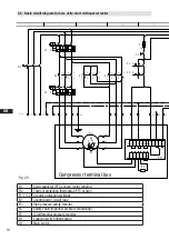
Page 18: ...1 L1 N N 43 43 11 12 14 L S M X2 1 2 3 4 5 6 7 F1 1 F1 2 8 R2 4A F2 S1 9 10 MP10 11 5 5 Basic circuit diagram for star delta start with special motor Fig 20 R1 Cold conductor PTC sensor motor winding...

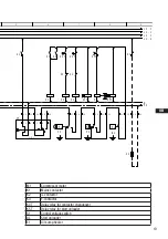
Page 19: ...K1 K3 P F3 K4T K3 K2 17 K4T K2 K3 18 19 K4T P F4 20 K5T AL 21 22 K5T P B1 23 24 K1 25 E1 26 L1 1 L2 1 L3 1 L1 2 N PE M1 Compressor motor K1 Mains contactor K2 contactor K3 Y contactor K4T Delay relay...

Page 20: ...LED lights red The hot gas side of the compressor can also be protected against overtemperature using a thermal protection thermostat accessory The H2 LED red is provided for the protection function T...

Page 21: ...connection 1 or 2 Release the hot gas temperature sensor if installed 3 or 4 2 Restore the power supply L1 or S1 ON Function check of motor temperature sensor operational ON Function check of hot gas...

Page 22: ...n the compressor is started the refrigerant contained in the oil evaporates due to the decline in pressure This can result in oil foaming and oil exodus which can result in oil hammer in certain circu...

Page 23: ...allation side The compressor has undergone trials in the factory and all functions have been tested There are therefore no special running in instructions Check the compressor for transport damage 6 2...

Page 24: ...en before starting the compressor Check that the safety and protection devices pressure switch motor protection electrical con tact protection measures etc are functioning properly Switch on the compr...

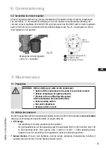
Page 25: ...h on lock 6 8 Connection of oil level regulator Oil level regulation systems have proven themselves with parallel circuits of several compressors The connection 0 is provided for installing an oil lev...

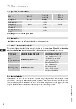
Page 26: ...his oil type should be used as a preference Alternatives are stated in the extract from our lubricants table below Refrigerants GEA Bock standard oil types Recommended alternatives HFC e g R134a R407C...

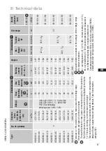
Page 27: ...7 152 42 1 5 8 69 66 63 HG4 650 4 S 56 6 67 9 34 18 4 107 140 155 1 2 3 2 4 380 420 V Y YY 3 50 Hz PW 440 480 V Y YY 3 60 Hz PW PW Part Winding Winding ratio 66 33 L M H 5 Tolerance 10 relative to the...

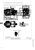
Page 28: ...st L Brazing connection L L tanschlu N Anschlu Leistungsregler Connection capacity controller O Anschlu lspiegelregulator Connection oil level regulator P Anschlu l Differenzdrucksensor Connection oil...

Page 29: ...sure switch OIL 7 16 UNF D Connection oil pressure switch LP 7 16 UNF D1 Connection oil return from oil separator 1 4 NPTF E Connection oil pressure gauge 7 16 UNF F Oil drain M22 x 1 5 H Oil charge p...

Page 30: ...pressor HG4 complies with the basic requirements of Appendix II 1B of the Machinery Directive 2006 42 EC Applied harmonised standard EN 12693 2008 and the corresponding standards referenced A partly c...

Page 31: ...estions about installation operation and accessories please contact our techni cal service or specialist wholesaler and or our representative The GEA Bock service team can be contacted by phone with a...

Page 32: ...4 0 Fax 49 7022 9454 137 refrigeration gea com www gea com We live our values Excellence Passion Integrity Responsibility GEA versity GEA Group is a global engineering company with multi billion euro...

Reviews: