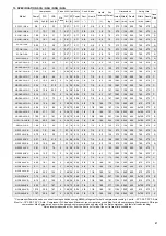
13. SPECIFICATION NSE NCE
Combined Compressors Fans 230V/1ph/50Hz
Conn. Sizes
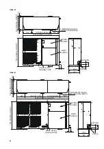
Dimensions
Fixing Ctrs
Power* FLC
LRA
FLC SC Power Suct.
Liquid.
Liquid
Receiver
Dry
Weight
Height Width Depth
Width Depth
Model
(kW) 3ph (A) 3ph (A)
No.
Fans
(A) (A)
(kW)
( “ )
( “ )
(L)
(kg)
(mm) (mm)
(mm)
(mm)
(mm)
Case
Size
NSE15-3MX-A
1.92
4.9
26
1
1
2.12 0.19
3/8
7/8
6.2
119
573
1128
505
749
475
A
NSE19-3MX-A
2.26
6.5
32
1
1
2.12 0.19
3/8
7/8
6.2
122
573
1128
505
749
475
A
NSE21-3MX-A
2.63
7.2
40
1
1
2.12 0.19
3/8
7/8
6.2
126
573
1128
505
749
475
A
NSE26-3MX-B
3.02
8.85
46
1
1.55 3.2
0.25
1/2
7/8
6.2
135
675
1128
505
749
475
B
NSE30-3MX-B
3.52
10.3
49.3
1
1.55 3.2
0.25
1/2
7/8
6.2
144
675
1128
505
749
475
B
NSE38-3MX-B
4.55
12.8
65.5
1
1.55 3.2
0.25
1/2
7/8
6.2
145
675
1128
505
749
475
B
NSE45-3MX-B
5.36
13.1
74
1
1.55 3.2
0.25
1/2
7/8
6.2
148
675
1128
505
749
475
B
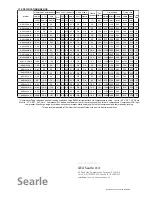
NCE56-3MX-D
6.20
15.4
99
2
3.1 6.4
0.50
5/8
1 1/8
18.0
160
1194 1560
600
810
570
D
NCE75-3MX-D
8.17
21.7
127
2
3.1 6.4
0.50
5/8
1 1/8
18.0
171
1194 1560
600
810
570
D
NCE92-3MX-E
10.3
25.1
167
4
6.1 12.8 1.00
7/8
1 1/8
18.0
207
1194 2260
600
2x750
570
E
NCE110-3MX-E
12.68
29.2
198
4
6.1 12.8 1.00
7/8
1 1/8
18.0
216
1194 2260
600
2x750
570
E
NSE9-3LX-A
1.98
6.0
40
1
1
2.12 0.19
3/8
7/8
6.2
123
573
1128
505
749
475
A
NSE11-3LX-A
2.41
6.5
32
1
1
2.12 0.19
3/8
7/8
6.2
122
573
1128
505
749
475
A
NSE13-3LX-A
2.65
8.0
52
1
1
2.12 0.19
3/8
7/8
6.2
134
573
1128
505
749
475
A
NSE15-3LX-A
3.26
10.0
64
1
1
2.12 0.19
3/8
7/8
6.2
135
573
1128
505
749
475
A
NSE18-3LX-A
3.9
12.0
74
1
1
2.12 0.19
3/8
7/8
6.2
141
573
1128
505
749
475
A
NCE24-3LX-D
4.82
16.1
99
2
3.1 6.4
0.50
5/8
1 1/8
18.0
161
1194 1560
600
810
570
D
NCE33-3LX-D
6.86
22.3
134
2
3.1 6.4
0.50
5/8
1 1/8
18.0
161
1194 1560
600
810
570
D
NCE40-3LX-D
8.35
25.1
159
2
3.1 6.4
0.50
5/8
1 1/8
18.0
171
1194 1560
600
810
570
D
NCE48-3LX-D
10.49
30.6
187
2
3.1 6.4
0.50
5/8
1 1/8
18.0
181
1194 1560
600
810
570
D
* Compressor Power based on nominal running conditions using R404A refrigerant for both compressors running. L units : -35°C SST, 32°C Amb,
M units : -10°C SST, 32°C Amb. Compressor FLC based on Maximum run current at any condition, for both compressors. Compressor LRA is per
compressor. Max Surge amps occur when second compressor starts on delay with the first compressor and fan(s) already running.
** Noise levels measured at 10m from the front air off side of the unit in free field conditions.
Searle
Number 272-000-310 Issue Oct 08/02
GEA Refrigeration
GEA Searle Ltd
20 Davis Way, Newgate Lane, Fareham, PO14 1AR
Tel. +44 (0) 1329 823344, Fax +44 (0) 1329 821242
sales@searle.co.uk, www.searle.co.uk
Summary of Contents for Searle NSQ Series
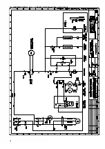
Page 10: ...11a SCQ All Units 1MX A SCQ 611 06 XXX W Single Phase with AC Fans 10...
Page 11: ...11b SCQ All Units 3MX A SCQ 613 06 XXX W Three Phase with AC Fans 11...
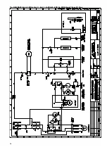
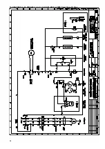
Page 14: ...11e NSQ NSE15 1MX A 44 611 16 XXX W ZB15 Single Phase with AC Fans 14...
Page 16: ...11g NSQ NSE19 to 26 1MX A B or C 44 611 06 XXX W ZB19 to ZB26 Single Phase AC Fans 16...
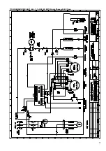
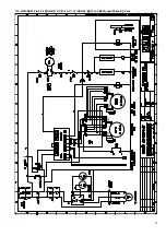
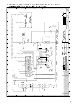
Page 18: ...11i NSQ NSE15 to 45 3MX A B C 44 613 06 XXX W ZB15 to ZB45 Three Phase AC Fans 18...
Page 20: ...11k NDQ 30 to 45 3MX S C 44 613 XDX W ZBD30 to ZBD45 Three Phase AC Fans 20...
Page 21: ...11l NCQ NCE 56 to 110 3MX S D E 2 3 44 633 16 XXX W ZB56 to ZB11 Three Phase AC Fans 21...
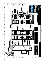
Page 22: ...11m NSQ NSE 15 to 30 1MX S A B C 2 3 44 611 ST2 Layout Diagram 22...
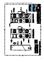
Page 23: ...11n NSQ NSE 09 to 18 3LX S 15 to 45 3MX S A B C 2 3 44 613 ST2 Layout Diagram 23...
Page 24: ...11o NCQ NCE 24 to 48 3LX S 56 to 110 3MX S D E 2 3 44 633 3 ST2 Layout Diagram 24...
Page 25: ...12 DIMENSIONS Case A B C 25...

