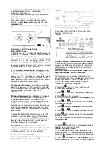
5
ISOLATED BEFORE MAINTENANCE WORK IS
UNDERTAKEN
Oil Charge
The compressors are pre charged with Polyolester oil.
Following initial start-up, some of this oil will migrate to
other areas of the system. Ensure the oil charge in the
system is adequate as follows :-
The following routine maintenance is required:
Every 3-6 months
The condenser should be cleaned with a soft brush to
ensure correct operation of the condensing unit. When the
condenser coil is obstructed by dirt or rubbish, the unit will
experience high condensing temperatures which will result in
higher running costs, loss of compressor efficiency and
ultimately overheating of the compressor and/or condenser
fans.
•
N2CQ ‘M’ models utilise an oil balance line between
compressors, ensure the oil balance line sightglass
level is 1/2 full when the compressors are not running.
•
N2CQ ‘L’ models are fitted with a separator reservoir,
ensure the oil charge is adequate to show in the upper
sight glass when the compressors are not running.
The pressure relief valve should be inspected for any
pressure release. If a release has occurred or there is a
requirement by the customer maintenance schedule the
relief valve should be changed.
Note: on N2CQ ‘M’ models with oil balance lines, the oil
level may show as empty when only one compressor is
running, this is normal. The true oil level will show when
both compressors are running, or both are at rest.
The PRV MUST be changed every 5 years.
Only suitable Polyolester oil, such as Mobil EAL
Arctic 22 CC (or equivalent), should be used.
Every 12 months
Check security of fixings, especially the fan and motor
mounting. Check refrigerant pipeline for damage and leaks.
Check motor (fans should rotate freely).
4. OPERATING LIMITS
The HP/LP switch must be set to prevent the unit from
operating outside of its application limits.
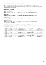
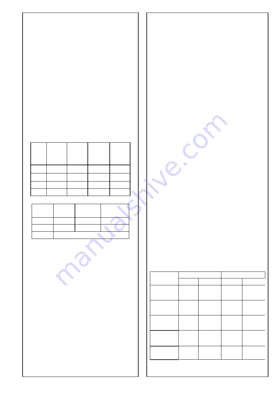
Check torque settings of compressor rotalock valves (see
table below).
The LP switch and Step Controller must not be set any
lower than the figures below:
When necessary
R404A & R407C
Clean the fins, guard and general casework. Care must be
taken when cleaning the fins to prevent damage. It is
recommended that a soft brush and mild detergent solution
be used.
Maximum HP
Cut out BarG
Minimum
SST °C
R404A
R407C
LP Cut out
BarG
R407C
Unit
Range
LP Cut out
BarG R404A
R404A
R407C
High-pressure spray washing of the unit must not be
undertaken, as damage to fin coatings and components will
occur. Low-pressure spray washing using specialist coil
cleaning solutions is recommended.
NS/NC-
'MX/S'
-20 2 1.7
25.2
NS/NC-
'LX/S/V'
-40 0.35 N/A 25.2
WARNING! SAFETY GOGGLES MUST BE WORN
DURING THIS OPERATION.
SCQ 'M'
-15
2.7
N/A
25.2
SCQ 'LX'
-35
0.7
N/A
25.2
6. INVALIDATION OF GUARANTEE
Searle accepts no liability, according to Searle's terms and
conditions of sale, for loss or damage arising as a result of:
R134A
Maximum HP Cut
out BarG
Minimum SST
°C
R134a
LP Cut out BarG
R134a
Unit Range
R134a
(i) Failure to install, set up or put to work any part of
equipment in the manner specified in the I&M
instructions, or
'MX/S' -20
0.37
14.4
(ii)
Failure to maintain the equipment in the manner
specified in the I&M instructions, or
'LX/S/V' -20
0.37
14.4
SCQ
Not Suitable for use with R134a
(iii)
Replacement parts, additional parts or accessories
supplied by persons other than Searle having been
incorporated into, or attached to the equipment, or
The LP differential setting must be set high enough to
prevent short cycling of the unit.
(iv) The equipment having been adapted for use, operated
or used in such a way as does not conform to Searle's
recommendations.
The LP Cut-Out pressure is the LP range setting minus
the LP differential setting.
The HP switch must be set at 0.9 x the PRV setting for all
refrigerants. As standard units are fitted with a PRV set to
27.6 BarG, the HP switch must not be set higher than
25.2 BarG.
7. Compressor Rotalock Valve Torques
Discharge Suction
Unit
Size Torque Size Torque
For R134a refrigerant a lower pressure 16 BarG PRV is
available, part number 200-200-528, the HP switch must
not be set any higher than 14.4 BarG.
SCQ7L & 8L
N/A
N/A
1" x 14
60 -70 Nm
SCQ13M to 27M
Multiple Evaporator Applications
SCQ9L & 14L
If the condensing unit is connected to multiple
evaporators operating independently of one another, it is
essential that the saturated suction temperature remains
within the operating limits when the minimum number of
evaporators are running.
1" x 14
60 - 70 Nm
1" x 14
60 - 70 Nm
SCQ31M
NSQ09L to 18L
60 – 70
90 – 100
1" x 14
1 1/4" x 12
Nm
Nm
NSQ15M to 45M
If the saturated suction temperature falls close to or below
the operating limits for medium temperature 'M' units
when the minimum number of evaporators are running,
the use of 'L’ units, or other Searle condensing unit
products should be considered.
NSQ24L to 40L
90 – 100
100 – 120
1 1/4" x 12
1 3/4" x 12
Nm
Nm
NSQ56M to 92M
NSQ48L
100 – 120
140 – 145
1 3/4" x 12
2 1/4" x 12
Nm
Nm
NSQ110M
5. MAINTENANCE
Check compressor rotalocks as described in the
maintenance section ‘Every 12 months’ (p4).
WARNING! THE UNIT MUST BE ELECTRICALLY
Note:
connection sizes are the threaded spud connection
Summary of Contents for Searle NSQ Series
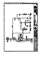
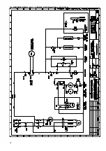
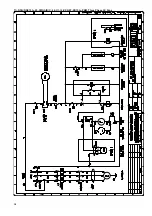
Page 10: ...11a SCQ All Units 1MX A SCQ 611 06 XXX W Single Phase with AC Fans 10...
Page 11: ...11b SCQ All Units 3MX A SCQ 613 06 XXX W Three Phase with AC Fans 11...
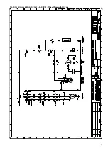
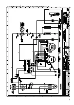
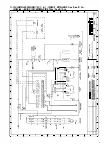
Page 14: ...11e NSQ NSE15 1MX A 44 611 16 XXX W ZB15 Single Phase with AC Fans 14...
Page 16: ...11g NSQ NSE19 to 26 1MX A B or C 44 611 06 XXX W ZB19 to ZB26 Single Phase AC Fans 16...
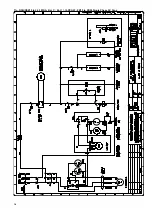
Page 18: ...11i NSQ NSE15 to 45 3MX A B C 44 613 06 XXX W ZB15 to ZB45 Three Phase AC Fans 18...
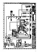
Page 20: ...11k NDQ 30 to 45 3MX S C 44 613 XDX W ZBD30 to ZBD45 Three Phase AC Fans 20...
Page 21: ...11l NCQ NCE 56 to 110 3MX S D E 2 3 44 633 16 XXX W ZB56 to ZB11 Three Phase AC Fans 21...
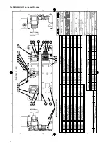
Page 22: ...11m NSQ NSE 15 to 30 1MX S A B C 2 3 44 611 ST2 Layout Diagram 22...
Page 23: ...11n NSQ NSE 09 to 18 3LX S 15 to 45 3MX S A B C 2 3 44 613 ST2 Layout Diagram 23...
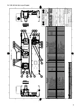
Page 24: ...11o NCQ NCE 24 to 48 3LX S 56 to 110 3MX S D E 2 3 44 633 3 ST2 Layout Diagram 24...
Page 25: ...12 DIMENSIONS Case A B C 25...


