background image

To adjust the second sensor, the process valve must be moved once to its end
positions by an external solenoid valve.

3.2.3

Control Top with Solenoid Valves

The control top with solenoid valves acts as a control top. The signalling takes
place in the same way as with the control top without solenoid valves. with the
difference being that the solenoid valve integrated in the base is operated in
accordance with the control signals. Depending on the design of the process
valve, up to 3 solenoid valves can be installed in the control top.
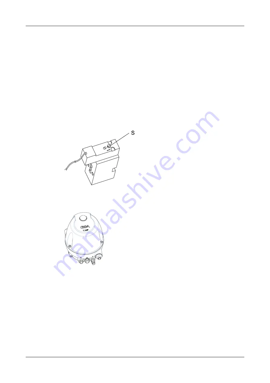
To provide compressed air support to the actuator spring, a pneumatic NOT logic
element can be used.
The control signals are given by the user's process control system or by
operating the solenoid valves manually. To do this, use a screwdriver to turn the
screw (S) from 0 to 1, see figure.

Fig.5

3.2.4

Control Top with Cap

Fig.6:

Control Top with Cap

According to protection class IP67 and/or 69k (EN 60529) the control top T.VIS
M-15 is suitable for use in this design and if the electrical and pneumatic
connections are installed correctly.
Observe the general instructions regarding ESD protection.

3.2.5

Safety Air Exhaust/Installation Position

To provide protection against excess pressure which can build up in the inside of
the control top, a vent plug (E2) is fitted in the base.

Description

Functional description


430BAL010697EN_2

20

15.04.2020

Summary of Contents for T.VIS M-15

Page 1: ...Control and feedback systems GEA T VIS M 15 Operating instruction Translation from the original language 430BAL010697EN_2...

Page 2: ...or reduced to an electronic medium of machine readable form without the express permission of GEA Tuchenhagen GmbH LEGAL NOTICE Word marks The designations T VIS VARIVENT ECOVENT STERICOM VESTA und LE...

Page 3: ...3 2 1 Operation Principle 19 3 2 2 Control Top without Solenoid Valves 19 3 2 3 Control Top with Solenoid Valves 20 3 2 4 Control Top with Cap 20 3 2 5 Safety Air Exhaust Installation Position 20 4 T...

Page 4: ...3 7 2 73 7 3 Checking Valve Actuation 74 7 4 Service Function 74 7 5 Adjusting the Sensor in the Control Top 74 7 5 1 Seat Valves Position of Sensor S1 Up 77 7 5 2 T smart Butterfly Valves 79 7 6 Adju...

Page 5: ...eral notes 105 13 Spare parts list control top type T VIS M 15 106 14 Spare parts list Switch bar T VIS M 15 111 15 Dimension sheet Control top type T VIS M 15 113 16 Dimension sheet Switch bar LFT R...

Page 6: ...430BAL010697EN_2 6 15 04 2020...

Page 7: ...the entire life cycle of the product When the location is changed or the product is sold make sure you also provide the Operating Instructions 1 1 2 Notes on the Illustrations The illustrations in the...

Page 8: ...n serious damage to the component or in the vicinity of the component The arrow identifies a precautionary measure you have to take to avoid the hazard Carry out the following steps Start of a set of...

Page 9: ...back signals coloured visualization of the valve position and status via the illuminated dome fitted on the control top In addition with T VIS M 15 you can monitor the non actuated position of the dou...

Page 10: ...tasks Order and cleanliness must be maintained at the work stations and in the entire area surrounding the component Personnel must wear suitable work clothing and personal protective equipment As the...

Page 11: ...e digit Explanation 1 digit Protection against solids 6 Dust tight 2 digit Protection against humidity 6 Protected against powerful water jets 7 Protected against temporary immersion 9k Protected agai...

Page 12: ...the valve unless the process plants have been emptied and depressurised Observe the accident prevention regulations and all local regulations 2 5 2 Environmental Protection Harm to the environment can...

Page 13: ...rvise the work Only allow specially trained personnel to carry out work on an explosion protected system When working on explosion protected equipment observe the standards DIN EN 60079 14 for gases a...

Page 14: ...t Sound knowledge in the following areas Mechanical equipment Electrical equipment Pneumatic system Authorization with regard to safety engineering standards to carry out the following tasks Setting d...

Page 15: ...electronics or result in data loss Do not carry out any welding work in the vicinity of the control top or make sure electronics are properly protected 2 9 1 Electrostatically Endangered Components an...

Page 16: ...the power supply and secure it against inadvertently being switched back on again Only allow a qualified electrician to carry out any work on the electrical power supply Check the electrical equipmen...

Page 17: ...s 7 Cap 47 Adapter module 8 Pneumatic block 50 Cable gland for external proximity switch 15 Clamp connection 63 Solenoid valves 21 Sound absorber 64 Logic element NOT optional 21 1 Throttle optional 6...

Page 18: ...hrottle optional for the infinitely adjustable setting of the closing velocity of the main stroke a supply air throttle optional for the infinitely adjustable setting of the opening velocity of the ma...

Page 19: ...module with its sensors is to determine the valve position on the basis of the position of the valve stem and to generate the corresponding feedback signals for this position in order to send them to...

Page 20: ...ring a pneumatic NOT logic element can be used The control signals are given by the user s process control system or by operating the solenoid valves manually To do this use a screwdriver to turn the...

Page 21: ...or in case of sealing problems pressure relief is ensured Fig 7 Control Top with Cap This vent plug is a safety device that must be handled as such Do not cover the vent plug When fitting the control...

Page 22: ...g gear and slings for transporting the package units control tops Observe the pictograms on the package The synthetic materials of the control tops are susceptible to breaking Take care when transport...

Page 23: ...xplanation 14 Feedback location T M 1 5 Control Top T VIS M 15 15 Control top type N without solenoid valve P 1 solenoid valve Y1 M 1 solenoid valve Y1 retrofittable Y2 Y3 N 2 solenoid valves Y1 Y2 2...

Page 24: ...l feedback signals 3 3 digital feedback signals with external proximity switch 17 Type of interface mode A AS Interface A B slave D DeviceNet B 24 V DC 3 wire PNP N 24 V DC 3 wire NPN 18 Solenoid valv...

Page 25: ...L Air connection metric 2 pin connector M12 AS i M Air connection metric M20x1 5 cable gland P Air connection Inch 5 pin connector M12 1 solenoid valve 2 feedback signals S Air connection Inch M20x1 5...

Page 26: ...e 2m with M12 junction box for screw connection L or U A T VIS for ASEPTOMAG valves Example TA15L8BAH A UC Certification UL CSA For indoor use and only for the type of interface connection A AS interf...

Page 27: ...terial PA Outside 6 35 mm Inside 4 3 mm Control air pressure max 8 bar min 2 bar Sound pressure level using sound absorber max 72 dB Technical data Materials Designation Description Housing PA 12 L Se...

Page 28: ...ule 24V DC Version Type designation 221 589 53 Technical data power supply Designation Description Nominal and supply voltage UV 24 V DC 20 15 Operating current for interface module 24V DC No load cur...

Page 29: ...C Connection terminals for conductor cross section up to 1 5 mm 5 4 Specifications for AS Interface Adapter Module Type designation 221 589 24 AS I MODUL Technical data power supply Designation Descr...

Page 30: ...1 x 32 mm Housing material PA6 GF30 V0 connection 2 pin 0 5 1 5 mm Pin strip 10 pin without 7 8 grid 3 5 mm Vibration proofness 55 Hz 1 mm Shock proofness 5 x g Protection class IP 20 Temperature rang...

Page 31: ...valve Y1 DO1 Activation of solenoid valve Y2 DO2 Activation of solenoid valve Y3 Technical data Design of I O module for T VIS Designation Description Dimensions 85 x 61 x 32 mm Housing material PA6 G...

Page 32: ...itch Switches 3 and 8 MAC ID address Switches 3 to 8 MAC ID address DIP 3 DIP 4 DIP 5 DIP 6 DIP 7 DIP 8 MAC ID OFF OFF OFF OFF OFF OFF 0 OFF OFF OFF OFF OFF ON 1 OFF OFF OFF OFF ON OFF 2 ON ON ON ON O...

Page 33: ...duce the opening speed of the main stroke on the central air supply P 603 042 Exhaust air throttle 21 1 with sound absorber 21 to reduce the closing speed of the main stroke on exhaust air connection...

Page 34: ...ent Technical data equipment Equipment Material no Proximity switch M12x1 in the lantern As per NAMUR normally closed contact 7 5 30 V DC Ambient temperature 20 70 C Protection class IP 67 Non metal c...

Page 35: ...bsorber G 1 4 Filter material stainless steel wool Ambient temperature 20 70 C max pressure 10 bar 933 174 Supply exhaust air throttle G 8 Filter material sintered stainless steel Pressure range 0 2 1...

Page 36: ...r opening the crate Under no circumstances should anyone stand under a suspended load Safety devices of the component may not work effectively during installation Reliably secure sections of the plant...

Page 37: ...air throttle N Air connection for spring force backup Only with logic element NOT Y1 Air connection for external main stroke connection with plug 23 23 Plug Control air pressure can be present at the...

Page 38: ...connection with plug 23 Y2 Air connection for lifting the valve disk Y3 Air connection for lifting the double disk or for the main stroke of an external process valve 23 Plug Control air pressure can...

Page 39: ...nection for lifting the double disk or for the main stroke of an external process valve 23 Plug Control air pressure can be present at the plugs for the air connections Before removing a sealing plug...

Page 40: ...permissible operating voltage Carry out the following steps 1 Release the cheese head screws 25 and take off the cap 7 2 Pass the cable 6 12 mm through the cable gland 24 and connect it to the termin...

Page 41: ...ent connector 3 3 Close the terminal box The electrical contact is established by pressing on the upper part 4 Tighten the locking screw 24 43 Done Connector 24 2 M12 2 pin for ASI Fig 16 Carry out th...

Page 42: ...ternal Proximity Switch 170 Fig 17 Caution Only use proximity switches specified in the chapter Technical data see Chapter 5 Page 23 Carry out the following steps 1 Insert the cable 3 7mm through the...

Page 43: ...ack of end position 3 L UV L reference potential 4 S1 Feedback of non actuated position 5 PV1 Actuation of solenoid valve Y1 Carry out the following steps 1 Connect cable via air connector M12 5 pole...

Page 44: ...ct cable via air connector M12 8 pole Done 6 4 4 3 Interface module with 2 sensors Fig 20 Interface module with 2 sensors Material no 221 589 53 see Chapter 13 Page 106 Description of the function of...

Page 45: ...3 double disk lifting stroke 17 18 Y Common L With contact bridge for solenoid valves 18 19 Internal contact bridge 19 20 24 V DC Auxiliary power The feedback signal for the non actuated position of t...

Page 46: ...2 Description of the function of the terminals Terminal Designation Functional description 1 ASI Communication and supply 2 ASI Communication and supply Light emitting diode LED Colour green Indicatio...

Page 47: ...nnector M12 2 pole Done 6 4 6 Electrical DeviceNet Wiring 6 4 6 1 Plug M12 5 pin 24 2 Fig 23 5 pin M12 connector A coded device connector and view of male connector Corresponding cable sockets part no...

Page 48: ...V Supply 4 V Supply Light emitting diode LED Colour green Indication permanent light working Indication flashing ready for communication Colour red Indication permanent light communication not possibl...

Page 49: ...6 4 7 Wiring Diagram for 24 V DC Control Systems with P Logic Fig 25 Assembly and installation Electrical connections 430BAL010697EN_2 15 04 2020 49...

Page 50: ...supplying with jumper WD 4 Common L selected for solenoid valves WD 5 Higher level PLC I O level 24VDC WD 6 24 V DC power supply WD 7 Grounding Hint If electrically isolated circuits are used for val...

Page 51: ...6 4 8 Wiring Diagram for 24 V DC Control Systems with N Logic Fig 26 Assembly and installation Electrical connections 430BAL010697EN_2 15 04 2020 51...

Page 52: ...valves WD 5 Higher level PLC I O level 24VDC WD 6 24 V DC power supply WD 7 Grounding Hint If electrically isolated circuits are used for valve actuation and feedback the jumper between terminal 17 an...

Page 53: ...Fig 27 Assembly and installation Electrical connections 430BAL010697EN_2 15 04 2020 53...

Page 54: ...6 4 10 Wiring Diagram for T VIS M 15 24 V DC Check the assignment of the wires before connecting the cables Assembly and installation Electrical connections 430BAL010697EN_2 54 15 04 2020...

Page 55: ...Fig 28 Assembly and installation Electrical connections 430BAL010697EN_2 15 04 2020 55...

Page 56: ...osition that deviates from its adjusted actuated positions flashing yellow Valve idle no indication There is a power failure if no signal is displayed for more than 5 seconds 6 6 Mounting the Control...

Page 57: ...be pointing vertically upwards The vent plug E2 must never be covered Notice The permanent magnet on the switch bar is fragile Damage to the permanent magnet Protect the permanent magnet against impa...

Page 58: ...from the switch bar Requirement Pay attention not to kink the air hoses when mounting the control top Carry out the following steps 1 Check that the switch bar 1 is firmly in place If necessary tight...

Page 59: ...components against the magnetic fields from the switch bar Carry out the following steps 1 Fit the bearing 201 into the locking screw 198 Fig 31 2 Fit the O ring 210 3 Use a face spanner to screw the...

Page 60: ...plug 23 since the control top T VIS M 15 has an inner air duct Fig 32 9 Perform commissioning see Chapter 6 Page 36 and Chapter 7 Page 73 Done Assembly and installation Mounting the Control Top to Dif...

Page 61: ...Protect the components against the magnetic fields from the switch bar Carry out the following steps 1 Screw the switch bar 1 into the actuator A and tighten using a mandrel 6 torque 22 Nm Fig 33 2 F...

Page 62: ...cal components Protect the components against the magnetic fields from the switch bar Carry out the following steps 1 Complete the T VIS mounting base 198 with O rings 29 101 and a plain bearing 202 F...

Page 63: ...the T VIS control module B connection A 4 2 on the actuator is closed 6 Carry out commissioning see chapter Commissioning Done Assembly and installation Mounting the Control Top to Different Valves 43...

Page 64: ...lds from the switch bar Carry out the following steps 1 Complete the T VIS mounting base 198 with O rings 29 101 and a plain bearing 202 Fig 35 2 Screw the mounting base 198 into the actuator A4 and t...

Page 65: ...e air connection Y1 on the control top to connection A4 2 on the actuator with an air hose L 8 Perform commissioning see Chapter 6 Page 36 and Chapter 7 Page 73 Done Assembly and installation Mounting...

Page 66: ...estroy electronic or mechanical components Protect the components against the magnetic fields from the switch bar Carry out the following steps 1 Place O rings 139 2 in the adapter 139 at the bottom s...

Page 67: ...lbft 8 Align the pneumatic and electrical connections in accordance with the valve block configuration 9 As internal air guiding is not possible on VESTA valves connect the air connection Y1 on the co...

Page 68: ...T VIS mounting base 198 with O rings 29 101 and a plain bearing 202 Fig 37 Fig 38 2 Screw the adapter T VIS E SHO 139 into the actuator with open end wrench on wrench surface 139 1 and tighten 3 Screw...

Page 69: ...the air connection Y1 on the control top to connection A 4 2 on the actuator with an air hose L 8 Perform commissioning see Chapter 6 Page 36 and Chapter 7 Page 73 Done Assembly and installation Mount...

Page 70: ...switch bar Carry out the following steps 1 Screw the switch bar 1 into the piston rod A4 1 and tighten with open end wrench SW13 at 1 1 torque 2 Nm 2 Fit the control top B over the switch bar 1 and o...

Page 71: ...s 1 Place the T VIS mounting base M with O rings M1 on the actuator A 4 and secure it with four M5 screws M 2 Fig 40 2 Screw the switch bar 4 Mat 221 589 87 into the piston rod A4 1 and tighten with o...

Page 72: ...Tops When replacing the control top observe the following warning note Caution Spring tension being released if the wrong switch bar is used When a valve is used with the wrong type of switch bar ther...

Page 73: ...will not accept any liability for malfunctions The risk is borne solely by the operating company Commissioning For commissioning the following principles apply Only allow properly qualified staff to...

Page 74: ...Y1 Y2 and Y3 if fitted Fig 41 Y1 main actuator Y2 valve disk lifting Y3 double disk lifting Done 7 4 Service Function If maintenance must be conducted on a process valve that is fitted with a control...

Page 75: ...or or for checking the switching function make sure that no media are inside the valve Caution There is the risk of over tightening the pin screw 1 Therefore only turn the pin screw 1 with a torque of...

Page 76: ...valve actuated position of sensor S2 top Move the valve disk to the upper end position either by electrical or manual actuation of solenoid valve Y1 See chapter Switch on control air Fig 44 Carry out...

Page 77: ...f the sensor for the following valves VARIVENT ECOVENT STERICOM valve except valve type U and actuator selection A non actuated position of the valve is spring opening VARIVENT valve type U and actuat...

Page 78: ...yellow Setting the switchpoint Hint Turning the adjusting screw 1 clockwise moves the sensor upwards turning counter clockwise moves the sensor downwards Carry out the following steps 1 Moving the swi...

Page 79: ...lves 0 5 turns in clockwise direction Light emitting diode B at the interface module lights up yellow 2 Tighten the locking screw 2 torque 1 Nm 0 7 lbft 3 Cancel the actuation of solenoid valve Y1 The...

Page 80: ...rry out the following steps 1 Release the locking screw 2 2 Turn the adjusting screw 1 of the sensor S1 until light emitting diode A at the interface module lights up green 3 Move the sensor with the...

Page 81: ...3 Move the sensor with the adjusting screw 1 in the direction of the lower switching edge 4 of the switching range 3 until LED B flashes yellow Setting the switchpoint Carry out the following steps 1...

Page 82: ...3 and nut NI 2 Fig 51 2 Insert the preassembled part in the slot 4 1 in the lantern 4 with the mounting hole 1 1 facing in the direction of the housing 5 Fig 52 3 Turn the nut NI 2 in the slot 4 1 in...

Page 83: ...ulder of the cleaning connection in the direction of the actuator A 3 Fix the proximity switch holder in position with the countersunk screw Done Fitting the proximity switch Carry out the following s...

Page 84: ...id valve Y3 The LED must go out Done The proximity switch has now been adjusted and checked 7 7 Adjusting the Proximity Switch in the lantern of PMO Valve Type M 2 0 Fitting the proximity switch holde...

Page 85: ...e countersunk screw position the proximity switch holder in the slot in the lantern so that the point of the adjusting screw 6 rests on the shoulder of the upper balancer in the direction of the actua...

Page 86: ...10 which has already been electrically connected to the control top to the proximity switch using the cap nut M12 10 1 During operation the LED on the proximity switch must now light up Done Checking...

Page 87: ...of lower seat 1 c Solenoid valve Y3 lifting of upper seat These valves can be activated externally by signals from the PLC 2 The closed position of the lower seat is detected by a position measuring s...

Page 88: ...em interlock programmed in the PLC is working correctly by manually actuating the valve disk that shuts off the pipe of the valve which currently is not part of the cleaning circuit If interlocking is...

Page 89: ...rking correctly the CIP supply pump will be deactivated If the CIP supply pump or source for generating cleaning solution pressure is not deactivated immediately shut down the system and perform a pro...

Page 90: ...rvals All guards and hoods must be fitted as intended The installation location of the component must always be properly ventilated Structural changes to the component are not permitted Report any cha...

Page 91: ...afety data sheets supplied by the detergent manufacturers Only use detergents which are not aggressive towards synthetic materials and the sealing materials used and which are non abrasive Cleaning Cl...

Page 92: ...to the maintenance or repair work going on Do not climb on the component Use suitable access aids and working platforms Wear suitable protective clothing Only use suitable and undamaged tools to carr...

Page 93: ...d when re assembling Protect open line ends with blind plugs against ingress of dirt Pack sensitive parts separately For longer periods of standstill observe the storage conditions see 10 2 Inspection...

Page 94: ...d optional NOT element 64 for pressure tight fit 2 Check sound absorbers 21 26 non return valve 26 1 and filter 5 1 for soiling Done 10 3 Removing the Control Top from the Valve Fig 65 Requirement Mak...

Page 95: ...63 and 2 control plates 65 and without or with 1 logic element NOT 64 or 1 solenoid valve 63 or without solenoid valve with 1 control plate 65 10 4 2 Removing the Cap Fig 66 Danger Electrical voltage...

Page 96: ...f burns from the solenoid valve Allow to cool before dismantling Carry out the following steps 1 Disconnect the cables of the solenoid valve from the terminals of the interface module 43 2 Undo the sc...

Page 97: ...be mounted upward The screws 66 are located in the lower mounting holes On ASEPTOMAG valves special types of the pneumatic block must be used Tighten the screws 66 to a max tightening torque of 1 Nm...

Page 98: ...reverse order Place the logic element NOT with adapter plate and seal on the pneumatic block 8 as shown in the illustration When inserting and tightening the screws be careful to use existing threads...

Page 99: ...43 and pull the adapter module 47 out of the interface module 43 by approx 7 mm in the direction of the arrow and then remove it from the base 5 Done Hint Assemble the adapter module in the reverse or...

Page 100: ...this case tighten screw 56 2 first 10 4 8 Removing the pneumatic block Requirement If only the O rings 42 and 55 must be changed then the solenoid valves 63 control plate 65 and element NOT 64 can re...

Page 101: ...valves Pneumatic block T VIS 15 NOT 3PV ASG material no 221 646 93 Pneumatic block T VIS 15 3PV ASG material no 221 646 92 Fig 75 Fig 76 Fig 77 Pneumatic block 8 2 for max 1 solenoid valve pneumatic b...

Page 102: ...rques 6 Screw in plug connection 2 0 Nm 21 Sound absorber 2 0 Nm 22 Locking screw 0 5 Nm 23 Plug 26 Sound absorber 2 0 Nm 42 O ring Carry out the following steps 1 Establish the pneumatic connections...

Page 103: ...O ring 54 Carry out the following steps 1 Take out the O rings 31 53 54 and replace them with new ones 2 Check that the control air can exit freely from the sound absorbers 21 26 filter 5 1 exhaust ai...

Page 104: ...ted immediately Yellow Actuation via process control system or the manual override device on the solenoid valve activated Cancel the actuation After connecting the power supply the valve position is i...

Page 105: ...the storage conditions see Chapter 4 Page 22 12 2 Disposal 12 2 1 General notes Dispose of the component in an environmentally safe manner Observe the statutory waste disposal regulations applicable a...

Page 106: ...13 Spare parts list control top type T VIS M 15 Fig 81 Spare parts list control top type T VIS M 15 430BAL010697EN_2 106 15 04 2020...

Page 107: ...lamp connection KU 221 507 08 221 507 08 221 507 08 21 Sound absorber G1 8 MS CV 933 175 933 175 933 175 22 Screw plug G1 8 PE HD 922 369 922 369 922 369 23 Plug PP 922 281 922 281 922 281 24 Cable gl...

Page 108: ...1 507 08 21 Sound absorber G1 8 MS CV 933 175 933 175 933 175 22 Screw plug G1 8 PE HD 922 369 922 369 922 369 23 Plug PP 922 280 922 280 922 280 24 Cable gland G1 2 PA 508 915 508 915 508 915 25 Adap...

Page 109: ...94 15 Clamp connection KU 221 507 08 221 507 08 221 507 08 21 Sound absorber G1 8 MS CV 933 175 933 175 933 175 22 Screw plug G1 8 PE HD 922 369 922 369 922 369 23 Plug PP 922 281 922 281 922 281 24 C...

Page 110: ...coded 47 1 AS interface adapter module 221 589 24 Connection type ASI 4E 4A connection to interface module 47 2 DeviceNet adapter module 221 589 22 Connection DeviceNet 4E 4A connection to interface m...

Page 111: ...14 Spare parts list Switch bar T VIS M 15 Fig 82 Spare parts list Switch bar T VIS M 15 430BAL010697EN_2 15 04 2020 111...

Page 112: ...butterfly valves type ECOVENT S 2 Switch bar BFV 7 1 4301 PA6 224 001697 For butterfly valves T smart 7 and 9 3 Switch bar LFT R 1 4301 PA6 see type For valves with lifting actuator R T_R L M_O 06 MT...

Page 113: ...1 Y2 Y3 E1 E2 and P refer to the Operating Instructions Control Top T VIS M 15 X supply voltage electric actuation and feedback S3 electrical connection for external proximity switch View without cap...

Page 114: ...6 Dimension sheet Switch bar LFT R T VIS M 15 for lifted valves Valve R T_R L M_O 06 MT T_R 08 M 2 0 Fig 84 Dimension sheet Switch bar LFT R T VIS M 15 for lifted valves 430BAL010697EN_2 114 15 04 202...

Page 115: ...0 210 221 618 26 316 EG 221 118 05 160 210 221 618 26 316 EH 221 119 05 160 210 221 618 26 316 BD5 221 119 06 140 110 221 618 26 316 BE5 221 119 07 140 110 221 618 26 316 CF5 221 119 10 140 110 221 61...

Page 116: ...1 618 29 453 SH6A 221 586 02 246 260 5 221 618 29 453 SK6A 221 586 03 246 260 5 221 618 29 453 SM6A 221 586 04 246 260 5 221 618 29 453 SN6A 221 586 05 246 260 5 221 618 29 453 EF6A 221 586 07 246 210...

Page 117: ...Short designation according to DIN ISO 1629 Ethylene Propylene Diene Rubber F Unit of measurement of temperature degree Fahrenheit FKM Material designation short designation according to DIN ISO 1629...

Page 118: ...Self learning installation During commissioning and maintenance the SET UP procedure carries out all the necessary settings for the generation of messages AF Specifications for the size of spanners w...

Page 119: ...Appendix 430BAL010697EN_2 15 04 2020 119...

Page 120: ......

Reviews: