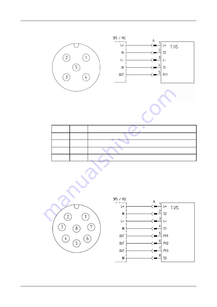
6.4.4.1 Plug M12 / 5-pin (24.5)
Fig.18:
5-pin M12 connector A-coded: device connector and view of male connector
Corresponding cable socket part no. 508-963.
1
L+
U
V
L+24 V DC supply voltage
2
S2
Feedback of end position
3
L-
U
V
L- reference potential
4
S1
Feedback of non-actuated position
5
PV1
Actuation of solenoid valve Y1
Carry out the following steps:
1.
Connect cable via air connector M12/5-pole.
®
Done.
6.4.4.2 Plug M12 / 8-pin (24.1)
Fig.19:
8-pin M12 connector A-coded: device connector and view of male connector
Assembly and installation
Electrical connections
430BAL010697EN_2
15.04.2020
43
Summary of Contents for T.VIS M-15
Page 6: ...430BAL010697EN_2 6 15 04 2020...
Page 53: ...Fig 27 Assembly and installation Electrical connections 430BAL010697EN_2 15 04 2020 53...
Page 55: ...Fig 28 Assembly and installation Electrical connections 430BAL010697EN_2 15 04 2020 55...
Page 119: ...Appendix 430BAL010697EN_2 15 04 2020 119...
Page 120: ......


