2.
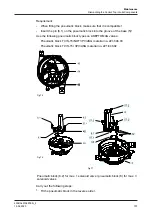
2. Screw the proximity switch M12 (8), together with the lock nut (11), into the
holder as far as the balancer (7).
Fig.62
®
Done.
Adjusting the proximity switch
Carry out the following steps:
1.
Unscrew the proximity switch by one full turn (360°) to set a gap (a) in the
range from 0.5 to 1.0 mm.
Fig.63
2.
Tighten the lock nut (11).
3.
Secure the connector (10), which has already been electrically connected to
the control top, to the proximity switch using the cap nut M12 (10.1).
®
During operation, the LED on the proximity switch must now light up
®
Done.
Checking the function
Carry out the following steps:
1.
Check the feedback function by actuating solenoid valve Y3.
®
The LED must go out.
®
Done
®
The proximity switch has now been adjusted and checked.
7.8
Test procedure for Tuchenhagen PMO valves type M / 2.0
Start-up
Test procedure for Tuchenhagen PMO valves type M / 2.0
430BAL010697EN_2
86
15.04.2020
Summary of Contents for T.VIS M-15
Page 6: ...430BAL010697EN_2 6 15 04 2020...
Page 53: ...Fig 27 Assembly and installation Electrical connections 430BAL010697EN_2 15 04 2020 53...
Page 55: ...Fig 28 Assembly and installation Electrical connections 430BAL010697EN_2 15 04 2020 55...
Page 119: ...Appendix 430BAL010697EN_2 15 04 2020 119...
Page 120: ......


