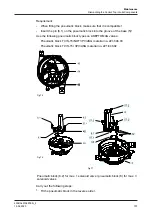
4.
Clamp (15)
5.
Lock nut (3), if an external proximity switch (170) is fitted
6.
Screw connection to base (5) and in the terminal strip of the interface module
(43), if an adapter module (47) is fitted
7.
Locking screw of the adjusting screws (43.1)
8.
Cap nut of the cable gland (24.1)
9.
Screw connection between cap (7) and base (5)
10.
Check the housing for mechanical damage.
11.
Plug (23)
Checking solenoid valves and sound absorbers
1.
Check solenoid valves (63) and optional NOT element (64) for pressure-tight
fit.
2.
Check sound absorbers (21, 26), non-return valve (26.1) and filter (5.1) for
soiling.
®
Done
10.3
Removing the Control Top from the Valve
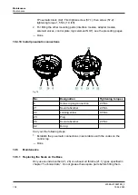
Fig.65
Requirement:
•
Make sure that the solenoid valve is not actuated.
Hint!
The pneumatic and electrical connections can remain on the control
top.
Carry out the following steps:
1.
Release the screw connection (39) and remove the clamp ring (15).
2.
Pull the control top vertically off the valve.
®
Light-emitting diode A (green) will go out and light-emitting diode B will
flash yellow.
®
Done
Maintenance
Removing the Control Top from the Valve
430BAL010697EN_2
94
15.04.2020
Summary of Contents for T.VIS M-15
Page 6: ...430BAL010697EN_2 6 15 04 2020...
Page 53: ...Fig 27 Assembly and installation Electrical connections 430BAL010697EN_2 15 04 2020 53...
Page 55: ...Fig 28 Assembly and installation Electrical connections 430BAL010697EN_2 15 04 2020 55...
Page 119: ...Appendix 430BAL010697EN_2 15 04 2020 119...
Page 120: ......


