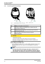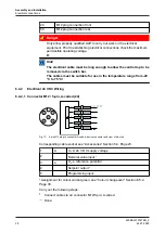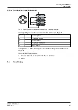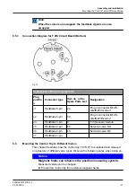
To operate the control top, take off the cap and press the plus/minus buttons
directly on the circuit board (A).
Observe the general instructions regarding ESD protection.
Operation see Section 8.2, Page 42.
3.1.4
Function of the Buttons
Automatic end position programming and manual mode are generally activated
using the buttons in or under the cap. For safety reasons, the buttons are only
enabled within a specific time window after activation of the operating voltage.
During this time window, functions can be started. The buttons are automatically
locked again after the allowed time has expired.
In manual mode the stroke of the actuator can be changed locally in 5 % steps in
the direction of the START or END position using the buttons in or under the cap.
The buttons in the cap can also be used to make customer-specific parameter
settings for the positioner.
3.1.5
Safety Air Exhaust/Installation Position
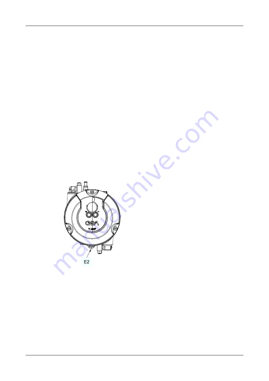
To provide protection against excess pressure which can build up in the inside of
the control top, a vent plug E2 is fitted in the base. In operating mode, the
exhaust air from the lifting actuators is discharged via this vent plug. In the
unlikely event of a damaged solenoid valve or in case of sealing problems,
pressure relief is ensured.
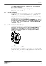
Fig.7:
Control top (standard variant in IP66)
This vent plug is a safety device that must be handled as such. Do not cover the
vent plug. When fitting the control top note that the installation position of the vent
plug E2 must never be pointing vertically upwards.
Description
430BAL010747EN_3
24.07.2020
17
Summary of Contents for T.VIS P-15
Page 65: ...Appendix 430BAL010747EN_3 24 07 2020 65 ...
Page 66: ......


