background image

STOP POSITION

HINGE

Your built-in oven is packed with a shipping base pad on
the bottom of the unit.  The lower front trim is shipped
separately and should not be used until you are ready to
install the oven with door removed.  See Step 2.

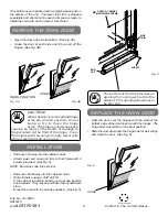
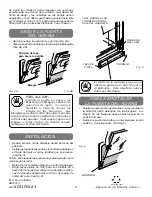
Open the door to the broil position.  (See Fig. 4A).

Grasp the door at each side and lift up and off the
hinges. (See Fig. 4B).

6

SCREW

END
CAP

SIDE

TRIM

OVEN TO CABINET

MOUNTING SCREWS

*

Fig. 5

BROIL POSITION

Fig. 4A

HINGE

Fig. 4B

When the door is removed and hinge
arms are at broil position, do not
bump or try to move the hinge
arms.  The hinges could snap back

causing an injury to the hands or damage to
the porcelain on the front of the range.  Cover
the hinges with toweling or empty towel rolls
while working in the oven area.

HINGE

CAUTION:

REMOVE THE OVEN DOOR

• Slide oven 3/4 way into the cabinet cutout.
• Attach lower end caps and trim to front frame with 3

screws provided.  (See Fig. 5).

NOTE:  End caps snap into side trim.

• Slide oven all the way into the cabinet cutout.
• Drill pilot holes using a 3/32" drill bit.

If the cabinet is particle board you must use particle
board screws.  They may be purchased at any hardware
store.

• Mount the oven with the screws supplied.  (See Fig. 5)

INSTALLATION

Recycled Paper

Pub. No. 31-10200
SR10313

229C

4053P056-1

-Printed in The United States-

Fig. 6

STOP POSITION

HINGE

REPLACE THE OVEN DOOR

Hold the door over the hinges with the slots at the
bottom edge of the door lined up with the hinges.  The
hinge arms must still be in the broil position.

Slide the door down onto the hinges as far as it will go
and close the door.  (See Fig. 6).

The bottom of the trim provides an
opening for cooling air to enter the
cabinet.  This opening should never
be blocked.

STOP!

STOP!

Summary of Contents for 47065

Page 1: ...under the counter installation see page 5 See Figure 3 for cutout dimensions to install a single built in oven under approved cooktop models ELECTRICAL REQUIREMENTS This appliance must be supplied with the proper voltage and frequency and connected to an individual properly grounded branch circuit protected by a circuit breaker or fuse having amperage as noted on rating plate Rating plate is locat...

Page 2: ... box and the flexible conduit must be securely attached to the connector If the flexible conduit will not fit within the connector do not install the oven until a connector of the proper size is obtained Continued on next page NOTE TO ELECTRICIAN The 3 power leads supplied with this appliance are UL recognized for connection to larger gauge household wiring The insulation of these 3 leads is rated...

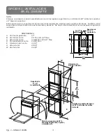
Page 3: ...t is level and straight There is no way to level the oven after installation A Cabinet Width 27 B Cutout Width 25 Min 25 1 4 Max C Cutout Height 27 5 8 Min 28 1 8 Max D Cutout Depth 23 5 8 Min E Cutout Location 32 1 2 H Overall Height 29 1 4 W Overall Width 26 3 4 DIMENSIONS OPTION 1 IN CABINET INSTALLATION 2 x 4 or Equivalent Runners 10 Allow 7 8 for overlap of oven over all edges of cutout Allow...

Page 4: ... is no way to level the oven after installation A Cabinet Width 27 Min B Cutout Width 25 Min 25 1 4 Max C Cutout Height 49 11 16 Min 50 1 8 Max D Cutout Depth 23 5 8 Min E Cutout Location 13 1 4 H Overall Height 51 1 4 W Overall Width 26 3 4 DIMENSIONS Fig 2 DOUBLE OVEN 4 Continued on next page Junction Box Locations Allow 7 8 for overlap of oven over all edges of cutout B E 10 56 MIN C Allow mini...

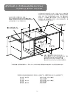
Page 5: ...N 28 1 8 MAX 25 MIN 25 1 4 MAX ALLOW 1 UNIT OVERLAP ALL EDGES USE 2 2 X 4 s OR EQUIVALENT RUNNERS SPACED 19 APART ON INSIDE SURFACES CENTERED IN OPENING FLUSH WITH TOP OF TOE PLATE 32 MIN FROM TOP OF CABINET TO TOP OF RUNNERS MUST BE MAINTAINED NOTE SEE BUILT IN OVEN INSTALLATION INSTRUCTIONS FOR COMPLETE INSTALLATION INSTRUCTIONS 5 Continued on next page OPTION 2 UNDER COUNTER INSTALLATION MODELS...

Page 6: ...NGE CAUTION REMOVE THE OVEN DOOR Slide oven 3 4 way into the cabinet cutout Attach lower end caps and trim to front frame with 3 screws provided See Fig 5 NOTE End caps snap into side trim Slide oven all the way into the cabinet cutout Drill pilot holes using a 3 32 drill bit If the cabinet is particle board you must use particle board screws They may be purchased at any hardware store Mount the o...

Page 7: ...nde está ubicado el desconectador principal del horno Consulte con las compañías de utilidades locales referente a los códigos eléctricos que se aplican en su área El no hacer el alambrado de acuerdo a los códigos vigentes podría resultar en condiciones peligrosas Si no existen códigos locales su horno tiene que ser alambrado y tener fusiblesquecumplanconlosrequerimientosdelosCódigos Eléctricos Na...

Page 8: ...ores o Cuando instale el horno en una casa de tipo Móvil o Cuando los códigos locales no permitan hacer tierra a través de neutral 1 Corte el alambre conector neutral blanco del forro Recorte el alambre conector neutral blanco para exponer el largo apropiado del conductor 2 Conecte el alambre para hacer tierra verde o cobre pelado al conductor para hacer tierra verde o cobre pelado de la residenci...

Page 9: ...rtes Esté seguro que los soportes del horno sean suficientemente sólidos para soportar 150 libras También esté seguro que el soporte del horno esté nivelado y derecho No hay forma de nivelar el horno después de que esté instalado OPCION 1 INSTALACION EN EL GABINETE Soportes de 2 x 4 o equivalente 10 Permita una salida del horno de 7 8 por todas las orillas del corte Permita un espacio de 20 a esqu...

Page 10: ...es Esté seguro que los soportes del horno sean suficientemente sólidos para soportar 150 libras También esté seguro que el soporte del horno esté nivelado y derecho No hay forma de nivelar el horno después de que esté instalado 4 Fig 2 DOUBLE OVEN Ubicación de caja de conexión Permita una salida del horno de 7 8 por todas las orillas del corte B E 10 56 MIN C Permita un espacio de 20 a esquinas ad...

Page 11: ... INSTRUCTIONS 5 MODELOS APROBADOS PARA LA INSTALACION BAJO EL GABINETE 47065 47069 47169 47465 47469 47466 48065 48069 JKP15AW JKP15BW JKP15WW JKP18AW JKP18BW JKP18WW JKS05BW LAS CONEXIONES DE GAS Y ELECTRICIDAD PARA UNA CUBIERTA DEBE INSTALARSE EN UNA POSICION ACCESIBLE A LA DERECHA SE DEBE MANTENER 32 MIN DE LA SUPERFICIE DEL GABINETE A LOS SOPORTES USE 2 SOPORTES DE 2X4 O EL EQUIVALENTE A 19 DE...

Page 12: ... paro no pase a llevarlos o trate de mover los brazos de las bisagras Las bisagras se podrían cerrar de golpe y causarle heridas en las manos o dañar la porcelana en el frente del aparato Cubra las bisagras con toallas o rollos vacíos de toallas cuando trabaje en el área del horno Fig 6 PARA REINSTALAR LA PUERTA DEL HORNO Sujete la puerta sobre las bisagras con las ranuras de la orilla del fondo a...

Reviews: