background image

– 7 –

*($SSOLDQFHVFRP

2SWLRQV

7KHOLJKWDERYHWKHVHOHFWHGSDGZLOOEH

21

WRLQGLFDWHZKLFK

237,21

KDVEHHQVHOHFWHG

67($03UHZDVK

8VHWKLVRSWLRQWRLPSURYHZDVKSHUIRUPDQFHZLWKKHDY\RUGULHGRQVRLOV7KLVRSWLRQLVDYDLODEOH

RQVRPH

 ZLWKDOOF\FOHVH[FHSW

5,16(21/<

PRGHOV

+27:$6+

 8VHWKLVRSWLRQWRLPSURYHZDVKDQGGU\SHUIRUPDQFHZLWKKHDY\RUGULHGRQVRLOV

+,7(03:$6+

 7KLVRSWLRQPXVWEHVHOHFWHGSULRUWRVWDUWLQJWKHF\FOH,WFDQQRWEHVHOHFWHGZLWK

5,16(21/<

RU

$''('+($7


&+,1$&5<67$/

F\FOH

RQVRPHPRGHOV 

+2767$57

 8VHWKLVRSWLRQWRLPSURYHZDVKDQGGU\SHUIRUPDQFHZKHUHLQOHWZDWHUWHPSHUDWXUHLVORZ

RQVRPHPRGHOV

+($7(''5<

  6KXWVRIIWKHGU\LQJKHDWRSWLRQ'LVKHVDLUGU\ZLWKRXWXVLQJHQHUJ\

/LJKW2))

 )RUIDVWHUDLUGU\\RXFDQSURSWKHGRRURSHQDIWHUWKH

&/($1

OLJKWLOOXPLQDWHV

+($7(''5<

 7XUQVWKHKHDWHURQIRUIDVWGU\LQJ7KLVZLOOH[WHQGWKHWRWDOUXQWLPHEHWZHHQDQGPLQXWHV

/LJKW21

 GHSHQGLQJRQWKHF\FOHVHOHFWHG

F\FOH

127(

&DQQRWEHVHOHFWHGZLWK

5,16(21/<

&21752/

<RXFDQORFNWKHFRQWUROVWRSUHYHQWVHOHFWLRQVIURPEHLQJPDGH<RXFDQDOVRORFNWKHFRQWUROV

/2&.

DIWHU\RXKDYHVWDUWHGDF\FOHWRSUHYHQWXQLQWHUUXSWHGF\FOHFKDQJHV

RQVRPH

 )RUH[DPSOHFKLOGUHQFDQQRWDFFLGHQWDOO\VWDUWWKHGLVKZDVKHUE\WRXFKLQJSDGVZLWKWKLVRSWLRQVHOHFWHG

PRGHOV

7R/2&.WKHGLVKZDVKHUFRQWURO

WRXFKDQGKROGWKH

+($7(''5<

SDGIRUVHFRQGV7KHOLJKWWRWKHOHIWRIWKH

+($7(''5<

SDGZLOOWXUQRQ

7R81/2&.WKHGLVKZDVKHUFRQWURO

WRXFKDQGKROGWKH

+($7(''5<

SDGIRUVHFRQGV

7KH

/2&.

OLJKWZLOOWXUQRII

'(/$<+2856

  <RXFDQGHOD\WKHVWDUWRIDZDVKF\FOHIRU

RU

KRXUVGHOD\WLPHRSWLRQVPD\YDU\E\PRGHO

7RXFKWKH

'(/$<+2856

SDGWRFKRRVHWKHQXPEHURIKRXUV\RXZDQWWRGHOD\WKHVWDUWRIWKH

F\FOHWKHQWRXFK

67$575(6(7

RQHWLPH

$VLQJOHEHHSZLOOFRQILUP

'(/$<+2856

KDVEHHQVHW7KH

GLVKZDVKHUZLOOFRXQWGRZQDQGVWDUWDXWRPDWLFDOO\DWWKHFRUUHFWWLPH7RXFKLQJ

67$575(6(7

D

VHFRQGWLPH

ZLOOFDQFHO

'(/$<+2856

DQGWXUQRIIWKHGLVKZDVKHU


127(

:KLOH

'(/$<+2856

LVDFWLYHDIWHUWKH

67$575(6(7

SDGKDVEHHQSUHVVHGWKHGLVKZDVKHU

ZLOOXSGDWHWKHUHPDLQLQJFRXQWGRZQWLPHRQWKHFRQWUROSDQHOEHIRUHWKHGLVKZDVKHUVWDUWVWKH

F\FOH)RUH[DPSOHLI

'(/$<+2856

LVVHOHFWHGWKHGHOD\KRXULQGLFDWRUZLOOPRYHIURP

WR

WR

WRRIIDVGHOD\WLPHHODSVHV

67$57


&ORVHDQGODWFKWKHGLVKZDVKHUGRRUDQGVHOHFWWKHF\FOHDQGGHVLUHGRSWLRQV7RXFKWKH

67$575(6(7

SDGRQHWLPHWREHJLQWKHF\FOH:DWHUEHJLQVWRILOOWKHGLVKZDVKHUDQGDSSUR[LPDWHO\

VHFRQGVODWHUWKHZDVKDFWLRQEHJLQV

127(

7KHGLVKZDVKHUUHPHPEHUV\RXUODVWF\FOHVR\RXGRQ·WKDYHWRUHSURJUDPHDFKWLPH

:KHQWKHGLVKZDVKHUGRRULVFORVHGDQGODWFKHGWKHFRQWUROSDQHOOLJKWVZLOOGLVSOD\WKHODVW

VHWWLQJVVHOHFWHG

,I\RXGRQ·WZDQWWRFKDQJHDQ\RIWKHVHWWLQJVVLPSO\WRXFKWKH

67$575(6(7

SDGRQFHWREHJLQWKHF\FOH

,IWKHGRRULVFORVHGWKHLQGLFDWRUOLJKWVZLOOWXUQRIILID

SDGLVQRWSUHVVHGZLWKLQWZRPLQXWHV

7RDFWLYDWHWKHGLVSOD\RSHQDQGFORVHWKHGRRURUWRXFKDQ\SDG

,IDSRZHUIDLOXUHRFFXUV

1250$/:$6+

DQG

+($7(''5<

ZLOODXWRPDWLFDOO\EHSURJUDPPHG

5(6(7

 7RFKDQJHF\FOHVDIWHUZDVKLQJVWDUWVSUHVVWKH

67$575(6(7

SDG7KLVZLOOFDQFHOWKHFXUUHQWO\

 UXQQLQJF\FOHDQGEHJLQSXPSRXW'XULQJWKLVWLPHWKH/('VRIWKHFXUUHQWO\VHOHFWHGF\FOH

 ZLOOIODVK2QFHWKHSXPSRXWLVFRPSOHWHWKHGLVKZDVKHUZLOOWXUQRII

  3UHVVWKH

67$575(6(7

SDGZKHQWKHGLVKZDVKHULVUXQQLQJWRFDQFHOWKHF\FOH7KHGLVKZDVKHUZLOO

  SXPSRXWDQGWXUQRIIDWWKHHQGRISXPSRXW7KH/('VRIWKHFXUUHQWO\VHOHFWHGF\FOHZLOOIODVK

  GXULQJSXPSRXW<RXFDQVHOHFWF\FOHVDQGRSWLRQVGXULQJSXPSRXW,I\RXSUHVV

67$575(6(7

  GXULQJWKHSXPSRXWSHULRGWKHSXPSRXWZLOOVWRSDQGDQHZF\FOHZLOOEHJLQ

(Continued next page)

Summary of Contents for GDWT1**V

Page 1: ...225 31 9220 GE and Profile Dishwashers PermaTuf Tub Models GLD28__V GLD45__V GLD46__V GLD49__V GLD56__V GLD57__V GLD58__V GLD77__V GLD78__V GLC5604V Technical Service Guide October 2011 GE Appliances Stainless Steel Tub Models GDWT1__V GHDT1__V GDWT3__V PDWT1__V ...

Page 2: ...ts use WARNING To avoid personal injury disconnect power before servicing this product If electrical power is required for diagnosis or test purposes disconnect the power immediately after performing the necessary checks RECONNECT ALL GROUNDING DEVICES If grounding wires screws straps clips nuts or washers used to complete a path to ground are removed for service they must be returned to their ori...

Page 3: ...ch 29 Heating Element 30 Inner Door Panel PermaTuf Tub Models 17 Inner Door Panel Stainless Steel Tub Models 24 Introduction 5 Lens 23 Lower Spray Arm 26 Mid Spray Arm 26 Motor Pump Assembly 33 Nomenclature 4 Outer Door Panel PermaTuf Tub Models 23 Outer Door Panel Stainless Steel Tub Models 17 Pocket Handle 21 Schematics and Wiring Diagrams 38 Service Mode 36 Sump Filter 28 Tactile Switch 19 Towe...

Page 4: ...Bisque CS Clean Steel SA Silver WH White Door with Black Control Panel Model Year Designator Model Year Designator Door 6 Stainless Door Feature Pack Controls T Top Control Product Type GLD GE Long Door PermaTuf Tub GLC Long Door GE Convertible Feature Pack Serial Number The first two characters of the serial number identify the month and year of manufacture Example TV123456S Oct 2011 T OCT V NOV ...

Page 5: ... harnesses Pocket handle and towel bar handle models Upper rack slides and tine spacing improvements Gray tubs and inner doors Entry Level Top Controls on Stainless Steel SS Tubs Top controls new console and tactile UI for control Limited pocket handle models Weights Dimensions Approximate Shipping Weight PermaTuf Tub 99 lb Stainless Steel Tub 115 lb Net Weight PermaTuf Tub 82 lb Stainless Steel T...

Page 6: ... 6 Throughout this manual features and appearance may vary from your model Control Features Continued next page and closing ...

Page 7: ...RQILUP 2856 KDV EHHQ VHW 7KH GLVKZDVKHU ZLOO FRXQW GRZQ DQG VWDUW DXWRPDWLFDOO DW WKH FRUUHFW WLPH 7RXFKLQJ 67 57 5 6 7 D VHFRQG WLPH ZLOO FDQFHO 2856 DQG WXUQ RII WKH GLVKZDVKHU 127 KLOH 2856 LV DFWLYH DIWHU WKH 67 57 5 6 7 SDG KDV EHHQ SUHVVHG WKH GLVKZDVKHU ZLOO XSGDWH WKH UHPDLQLQJ FRXQW GRZQ WLPH RQ WKH FRQWURO SDQHO EHIRUH WKH GLVKZDVKHU VWDUWV WKH F FOH RU H DPSOH LI 2856 LV VHOHFWHG WKH GH...

Page 8: ... 8 and closing Continued next page ...

Page 9: ...H RX FDQ DOVR ORFN WKH 2 FRQWUROV DIWHU RX KDYH VWDUWHG D F FOH WR SUHYHQW XQLQWHUUXSWHG F FOH FKDQJHV RQ VRPH RU H DPSOH FKLOGUHQ FDQQRW DFFLGHQWDOO VWDUW WKH GLVKZDVKHU E WRXFKLQJ SDGV ZLWK WKLV PRGHOV RSWLRQ VHOHFWHG 7R 2 WKH GLVKZDVKHU FRQWURO WRXFK DQG KROG WKH 7 5 SDG IRU VHFRQGV 7KH FRQWURO ORFN OLJKW ZLOO WXUQ RQ 7R 81 2 WKH GLVKZDVKHU FRQWURO WRXFK DQG KROG WKH 7 5 SDG IRU VHFRQGV 7KH FRQ...

Page 10: ... OLQH 7KH KRW ZDWHU PXVW EH EHWZHHQ DQG IRU EHVW ZDVK SHUIRUPDQFH 3XOO 8QLFRXSOH DQG LWV KRVHV FRPSOHWHO RXW IURP VWRUDJH FRPSDUWPHQW ORFDWHG DW UHDU RI GLVKZDVKHU WWDFK WKH 8QLFRXSOH FRQQHFWRU WR WKH IDXFHW DGDSWHU E GHSUHVVLQJ WKH FROODU DW WKH WRS RI WKH FRQQHFWRU KHQ 8QLFRXSOH LV DOO WKH ZD XS RQWR WKH DGDSWHU UHOHDVH WKH FROODU W ZLOO WKHQ VQDS LQWR SRVLWLRQ WR ORFN WKH 8QLFRXSOH LQ SODFH 7KH...

Page 11: ...e minimum temperature is not met an extended time will be added until the temperature is met or the time expires Partial drain and fill algorithm is used on Normal and Auto cycles only Auto Hot Start may cause the first prewash to repeat up to 4 times Steam enhancement is shown on the cycle chart Disabling steam will shorten the cycle time If Steam is selected in Normal or Auto cycles turbidity re...

Page 12: ...in Min Max Temp 135 F 158 F 158 F max 130 F 130 F 0 120 F 158 F Detergent Cup Yes Yes Yes Yes No Extend time 5 15 min 0 25 min 0 5 min Post Rinse Fill Time 63 sec 63 sec 63 sec 63 sec 63 sec Circulation Time 5 min 5 min 3 min 2 min 3 min Drain Time 75 sec 75 sec 75 sec 75 sec 11 sec Drain Overlap Time 3 10 sec 10 sec 10 sec 10 sec 0 Heater on Time 5 min 5 min 3 min 2 min 0 Min Max Temp 130 F 158 F...

Page 13: ... 13 Front View Component Locator Views Control Panel View Insulation Access Panel Continued next page Door Latch Control Panel Door Panel Control Assembly ...

Page 14: ...erior View Without Racks Detergent Rinse Module Compartment View Detergent Rinse Module Continued next page Detergent Compartment Compartment Lid Rinse Agent Cap Rinse Agent Outlet Indicator Window Inner Vent ...

Page 15: ...ft Side View Insulation Removed Bottom View Looking Up Spray Arm Heating Element Fill Hose Fill Funnel Front Back Drain Pump Tub TCO Coarse Filter Float Dome Fine Filter Hub Nut Door Spring Sump Water Valve Motor Turbidity Sensor Heater Flood Switch ...

Page 16: ... 16 Control Board Connector Locator View CN680 Model Select CN700 HMI Connector CN100 AC Power CN500 AC Load CN600 Turbidity Sensor CN700 CN100 CN500 CN600 CN680 ...

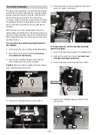
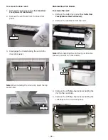
Page 17: ...sconnect the 2 wires from the detergent rinse module Continued next page Outer Door Panel Stainless Steel Tub Models The outer door panel on the stainless steel tub models must be removed to access the control board detergent rinse module control TCO tactile switch door switch vent and lens To remove the outer door panel 1 Remove the two 1 4 in hex head screws from the bottom of the front door pan...

Page 18: ...he vinyl shield must cover the control board cover before installing the inner door panel Vinyl Shield 3 Remove the single Phillips head screw that holds the control TCO to the control board cover 3 Disconnect the 2 wires from the detergent rinse module Continued next page Electrical Grade Silicone Grease Note When replacing the control TCO splice a new thermostat into the harness using connectors...

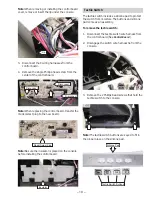
Page 19: ...lator is placed on the console before installing the control board Insulator Lip 3 Remove the 2 Phillips head screws that hold the tactile switch to the console Note The tactile switch buttons are keyed to fit in the proper place on the silicone pad Tactile Switch The tactile switch includes a silicone pad to protect the switch from moisture The buttons and silicone pad come as an assembly To remo...

Page 20: ...o remove the door switch assembly PermaTuf tub models 1 Disconnect the power supply to the dishwasher 2 Remove the inner door panel See Inner Door Panel PermaTuf Tub Models 3 Remove the 2 Phillips head screws from the door switch and remove the insulator Caution The door switch insulator must be in place when installing the door switch 4 Remove the bracket from the door switch Insulator Bracket 5 ...

Page 21: ...er off the outer door panel with a flat blade screwdriver 3 Remove the pocket handle through the front of the outer door Pocket Handle Vent Caution To prevent water leakage it is important to install the new vent on a clean panel using double backed tape If necessary remove excess adhesive on the panel before installing the new vent Adhesive Continued next page Towel Bar Handle To remove the towel...

Page 22: ...e the 2 Phillips head screws holding the duct to the vent body 4 Remove the 4 Phillips head screws holding the vent body to the inner door panel Vent Slot To remove the inner vent 1 Remove the inner door panel See Inner Door Panel PermaTuf Tub Models 2 Remove the vent foam from the inner door panel 3 Disengage the 3 tabs holding the vent to the inner door panel Note When installing the inner vent ...

Page 23: ...le step 4 4 Remove the 2 Phillips head screws from the bottom of the door 1 on each side Console To remove the console PermaTuf tub models 1 Remove the control board See Control Board 2 Remove the pocket handle or towel bar handle See Pocket Handle or Towel Bar Handle 3 Remove the outer vent See Vent 4 Disconnect the 4 wires from the door switch assembly Disconnect Disconnect 5 Pull the console ou...

Page 24: ...teel Tub Models 2 Disconnect the control board wiring harnesses See Control Board 3 If the installation allows pull the dishwasher out to access the door hinges 4 Insert 2 screwdrivers 1 on each side thru the door hinge bracket holes and secure under the dishwasher tub 6 Slide the inner door panel off the door hinges 5 Disconnect the spring to release tension from the door hinge Disconnect 5 Remov...

Page 25: ...est mode See Service Test Mode The first time the module is activated the lever slides up the right hand path of the connecting rod 1 This action releases the detergent cover 1 When deactivated the lever returns down the left hand path and comes to rest under the notch 2 in the center of the connecting rod At the second activation the lever lifts the connecting rod by the notch This action lifts t...

Page 26: ...washer 2 Remove the 1 4 in hex head screw from the spray arm Caution When installing the tub gasket run your finger over the gasket assuring it is smooth and even for a proper seal On the PermaTuf tub models a correctly installed gasket will have both ends of the gasket equally spaced from the bottom of the tub Do not stretch the gasket to make both ends meet the bottom of the tub Tub Gasket Chann...

Page 27: ...ad screw holding the arm to the conduit Fine Filter To remove the fine filter 1 Remove the lower spray arm See Lower Spray Arm 2 Rotate the hub nut counterclockwise Lift the hub nut off the fine filter 2 Disengage the right upper rack slide by pressing the lever up while pulling the rack out 3 Lift the fine filter off the spray arm hub 3 Remove the 1 4 in hex head screw from the spray arm Hub Nut ...

Page 28: ...ump filter prevents large particles from entering the sump To remove the sump filter 1 Remove the upper rack See Mid Spray Arm step 1 for PermaTuf tub models or steps 1 2 for stainless steel tub models 2 Remove the upper spray arm See Upper Spray Arm 3 Remove the fine filter See Fine Filter 4 Lift the tab on the spray arm hub while pulling the conduit back to remove Tab Tab Tab Conduit Sump Filter...

Page 29: ...The switch will only terminate the voltage to the water valve To remove the flood switch 1 Remove two 1 4 in hex head screws and the access panel Disconnect 3 Lift the coarse filter from the dishwasher Note Insure the spray arm bearing is in the proper location before assembly 4 Pull the flood switch out of the bracket 2 Disconnect the flood switch wiring harness 3 Remove the 2 Phillips head screw...

Page 30: ...ny prewash or rinse cycles and whether to adjust the wash or heat times By measuring the turbidity level the control module can conserve energy on lightly soiled loads by skipping unnecessary cycles If the soil level is high the control will add one or more rinse cycles and increase the wash and heat times as necessary Note If the turbidity sensor fails the unit will operate for the maximum amount...

Page 31: ...ll funnel O ring Water Inlet Valve The water inlet valve is electronically controlled and solenoid operated The flow of water is controlled by a rubber flow washer capable of maintaining a flow rate of 1 1 1 3 gallons per minute with incoming water pressure of 20 to 120 PSI The water valve is attached to a bracket located on the left side of the front brace The water valve is energized for approxi...

Page 32: ...he 4 Phillips head screws from the water inlet valve bracket Tab Caution To prevent water leakage assure the O ring is retained in the valve before installing the bracket O Ring 2 Remove the two 5 16 in hex head screws from the water inlet valve bracket 3 Slide the bracket down to disengage the tab that holds the bracket to the dishwasher frame ...

Page 33: ...ts installation 3 Lay the dishwasher on its back 4 Disconnect the 2 wires from the drain pump 5 Loosen the 5 16 in hex head screw then pull the drain pump off the sump Disconnect Disconnect Disconnect Motor Pump Assembly The motor pump assembly is located under the tub behind the sump assembly The motor utilizes a run capacitor rated at 10 fd The motor rotates clockwise as viewed from the terminal...

Page 34: ...ft side On stainless steel tub models the tub TCO is located under the tub behind the toe kick panel To remove the tub TCO PermaTuf tub models 1 Disconnect power 2 Remove the dishwasher from its installation 3 Lay the dishwasher on its back 4 Disconnect the 2 wires from the TCO 5 Remove the Phillips head screw from the TCO bracket Hanger 6 Slide the TCO off the bracket To remove the tub TCO stainl...

Page 35: ...Measure heater resistance at control Approx 15 20 ohms Yes No Are wire connections at heater and TCO OK No Repair connections Heater and TCO OK Check control circuit Yes Press button on TCO and listen for click Recheck circuit resistance Approx 15 20 ohms Yes No Heater stuck on Replace control Heater open TCO open or broken wire in circuit Replace part or repair wiring ...

Page 36: ...set keypad at any time The dishwasher will automatically exit service mode if the keypad is inactive for 5 minutes Front Control Models Key 1 Key 2 Key 3 Key 4 Key 5 Key 6 Key 7 Key 8 Key 9 Key 10 Key 11 DVKHG OLQHV LQGLFDWH NH SDG XVHG RQ VRPH PRGHOV KHQ NH SDG LV QRW YLVLEOH NH ORFDWLRQ H LVWV LQ VHUYLFH PRGH 6HUYLFH 0RGH 7HVW 0DWUL H 3UHVVHG FWLYDWHV 7LPH H 0DLQ 3XPS PLQ H X LOLDU 3XPS 0LQ H HW...

Page 37: ...il the maximum time has expired or another keypad is pressed Once the water valve is activated the microprocessor must perform a drain cycle to pump out the water before exiting the service mode Fast Control Model Reset Initiate a fast control model reset before replacing a nonresponsive control unit To initiate a fast control model reset Make sure the unit is powered off Press and hold the Start ...

Page 38: ...ITH RED TRACER CN800 FLASH CONNECTOR CN700 HMICONNECTOR TACTILE BOARD 1 2 3 4 5 6 7 8 9 10 11 12 13 14 15 1 2 3 4 TURBIDITY SENSOR CN600 1 2 3 4 MODEL SELECT CN680 4 3 2 1 YB NX SX OX NTC RECEIVER EMITTER TRANSMITTER CATHODE VCC 1 2 1 2 3 4 5 6 7 8 AC LOAD CN500 1 2 3 4 5 LIN DSM CN400 1 2 3 4 WR HEATING ELEMENT WR TUB TCO VX DRAIN PUMP WR RX M 30 BW DOOR INTERLOCK M PUMP MOTOR NX WR DETERGENT MOD...

Page 39: ...15 1 2 3 4 TURBIDITY SENSOR CN600 1 2 3 4 MODEL SELECT CN680 4 3 2 1 YB NX SX OX NTC RECEIVER EMITTER TRANSMITTER CATHODE VCC 1 2 1 2 3 4 5 6 7 8 AC LOAD CN500 1 2 3 4 5 LIN DSM CN400 1 2 3 4 WR HEATING ELEMENT WR TUB TCO VX DRAIN PUMP WR RX M 30 BW DOOR INTERLOCK BX M PUMP MOTOR NX WR DETERGENT MODULE 10 WR RY FLOOD PX 1200 2800 WATER WR 725 1200 BX L1 N WX G GY AC POWER CN100 SWITCH VALVE YX C N...

Page 40: ...UDLQ OLQH DPDJH FDXVHG DIWHU GHOLYHU LQFOXGLQJ GDPDJH IURP LWHPV GURSSHG RQ WKH GRRU 7KLV ZDUUDQW LV H WHQGHG WR WKH RULJLQDO SXUFKDVHU DQG DQ VXFFHHGLQJ RZQHU IRU SURGXFWV SXUFKDVHG IRU KRPH XVH ZLWKLQ WKH 86 I WKH SURGXFW LV ORFDWHG LQ DQ DUHD ZKHUH VHUYLFH E D XWKRUL HG 6HUYLFHU LV QRW DYDLODEOH RX PD EH UHVSRQVLEOH IRU D WULS FKDUJH RU RX PD EH UHTXLUHG WR EULQJ WKH SURGXFW WR DQ XWKRUL HG 6HU...

Reviews: