background image

Installation Instructions

9

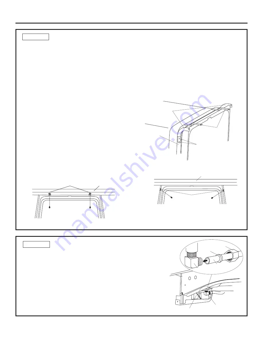
STEP 13  CONNECT WATER SUPPLY

Connect water supply line to 90

°

 elbow.

• Slide compression nut, then ferrule over end of

water line.

• Insert water line into 90

°

 elbow.

• Slide ferrule against elbow and secure with compression nut.

IMPORTANT

 –  Check to be sure that door spring

does not rub or contact the fill hose or water supply line. Test by
opening and closing the door. Reroute the lines if necessary.

Figure W

90

° 

Elbow

Ferrule

90

° 

Elbow

Hot Water

Supply Line

Compression Nut

Door Spring

In this step you will need the 2 Phillips special head
screws set aside prior to Step 1.

The dishwasher must be secured to the countertop or
the cabinet sides. When the underside of the counter-
top is wood, use Method 1. Use Method 2 when the
underside of the countertop is made of a material, such
as granite, that will not accept wood screws.

Tip: 

Prevent door panel and control panel damage.

Dishwasher must be positioned so the front panel and
control panel do not contact the adjacent cabinets or
countertop. Mounting screws must be driven straight
and flush. Protruding screw heads could scratch the
door panel or control panel and interfere with door
operation.

Method 1
Secure dishwasher to underside of wood countertop.

• Recheck alignment of the dishwasher in the cabinet.

Refer to Step 10, Figure Q and Step 11. Door panel
and/or control panel must not hit cabinets or
countertop.

• Fasten the dishwasher to the underside of the

countertop with the 2 Phillips special head screws
provided. Refer to Figure T.  Make certain screws are
driven straight and flush to prevent panel damage.

 STEP 12  POSITION DISHWASHER, SECURE TO COUNTERTOP OR CABINET

Figure V

Granite Countertop

Side Brackets

Brackets

 Wood Countertop

Figure T

Method 2
Secure dishwasher to cabinet sides

• Recheck alignment of the dishwasher in the cabinet.

Refer to Step 10, Figure Q and Step 11. Door panel
and/or control panel must not hit cabinets or
countertop.

• Fasten the dishwasher to the adjacent cabinets with

the 2 Phillips special head screws provided. Refer to
Figures U and V. Make certain screws are driven
straight and flush to prevent panel damage.

Bracket

Attachment

Screws
(2 Each

Side)

Side-

Mounting

Brackets

Countertop
Mounting
Brackets

Tub Frame

Figure U

Summary of Contents for gdwt708vbb

Page 1: ...he responsibility of the installer Product failure due to improper installation is not covered under the GE Appliance Warranty See warranty information Completion Time 1 to 3 Hours New installations require more time than replacement installations IMPORTANT The dishwasher MUST be installed to allow for future removal from the enclosure if service is required If you received a damaged dishwasher yo...

Page 2: ... must be tested for temperature and pressure Coupler for extending drain line if applicable TOOLS YOU WILL NEED Phillips head screwdriver 1 4 and 5 16 nutdriver 6 adjustable wrench Level Carpenters square Measuring tape Safety glasses Flashlight Bucket to catch water when flushing the line 15 16 socket optional for skid removal Gloves For New Installations Only Tubing cutter Drill and appropriate ...

Page 3: ...uire an air gap Is waste tee less than 18 above floor If the answer to either question is YES Method 1 MUST be used If the answers are NO either method may be used CABINET PREPARATION Drill a 1 1 2 dia hole in the cabinet wall within the shaded areas shown in Figure A for the drain hose connection The hole should be smooth with no sharp edges IMPORTANT When connecting drain line to disposer check ...

Page 4: ...ied with 120V 60Hz and connected to an individual properly grounded branch circuit protected by a 15 or 20 ampere circuit breaker or time delay fuse Wiring must be 2 wire with ground and rated for 75 C 176 F If the electrical supply does not meet the above requirements call a licensed electrician before proceeding Grounding Instructions Cable Direct This appliance must be connected to a grounded m...

Page 5: ...n accessible location such as under the sink Optional but strongly recom mended and may be required by local codes Water connection is on the left side of the dishwasher Install the hot water inlet line using no less than 3 8 O D copper tubing Route the line as shown in Figure F and extend forward at least 19 from rear wall Adjust water heater for 120 F to 150 F temperature Flush water line to cle...

Page 6: ...he National Electrical Code Section 422 and or local codes and ordinances Maximum power cord length is 6 feet Figure J Figure I STEP 3 REMOVE TOEKICK Remove the 2 toekick screws and toekick Set aside for use in Step 18 STEP 5A INSTALL DRAIN HOSE TO DISHWASHER DRAIN PORT Skip this step if drain hose has been pre installed In this step you will need the drain hose set aside prior to Step 1 Remove ho...

Page 7: ...ake sure drain hose is not kinked under the dish washer and there is no interference with the water line and wiring or any other component Do Not Push Against Front Door Panel With Knee Damage to The Door Panel Will Occur Figure O Tip Position water line and house wiring on the floor to avoid interference with base of dishwasher Figure N STEP 7 INSERT DRAIN HOSE THROUGH CABINET Turn the dishwasher...

Page 8: ...he cabinet The edges of the dishwasher door should be behind the cabinet frame and evenly aligned with the front face of cabinet doors Carefully open and close the door to ensure the door panel is not catching or rubbing on the cabinet frame Figure Q Door Fits and Swings Back Behind Cabinet Frame Correct Alignment Door Catches on Cabinet Frame Incorrect Alignment Figure R STEP 9A INSTALL SIDE MOUN...

Page 9: ...Mounting screws must be driven straight and flush Protruding screw heads could scratch the door panel or control panel and interfere with door operation Method 1 Secure dishwasher to underside of wood countertop Recheck alignment of the dishwasher in the cabinet Refer to Step 10 Figure Q and Step 11 Door panel and or control panel must not hit cabinets or countertop Fasten the dishwasher to the un...

Page 10: ... method Waste Tee Installation Method 1 Air gap with waste tee or disposer Disposer Installation Waste Tee Installation Method 2 Built in High drain loop with waste tee or disposer Disposer Installation Figure Z Figure AA Secure the drain hose to the air gap waste tee or disposer with clamps Note TOTAL DRAIN HOSE LENGTH MUST NOT EXCEED 10 FEET FOR PROPER DRAIN OPERATION Figure Y Hose Clamp Coupler...

Page 11: ...oise Turn on the sink hot water faucet and verify water temperature Incoming water temperature must be between 120 F and 150 F 120 F min temperature is required for best wash performance See Prepare Hot Water Line page 5 Add 2 quarts of water to the bottom of the dishwasher to lubricate the pump seal Turn on water supply Check for leaks Tighten connections if needed Remove protective film if prese...

Page 12: ...ater enters the dishwasher If water does not enter the dishwasher check to be sure that water and power is turned on Check for leaks under the dishwasher If leak is found turn power supply off then tighten connec tions Restore power after leak is corrected Check for leaks around the door A leak around the door could be caused by door rubbing or hitting against adjacent cabinets Reposition the dish...

Reviews: