background image

5

Standard Installation Preparation

B

Installation Instructions

Continued on following page

The Standard Installation of this Drop-In Range

is to hang by the countertop on the side metal

flanges under glass cooktop. 

This Range must

not be installed on a base or sub structure

(2”x 4” support).

If the construction of your cabinet cannot

provide a 1/4” flat area at the back of the

countertop opening, consider changing the

countertop to accomodate this dimension. If the

area is not flat, excess tension may be applied

to the glass cooktop causing breakage and

voiding the warranty.

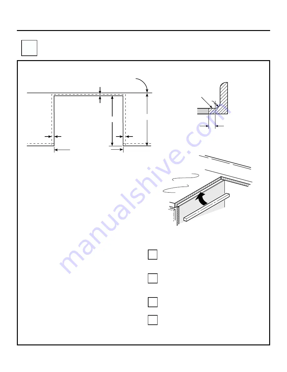
Center the 30” wide opening over the

adjacent cabinets and mark with a straight

edge.

Using a straight edge mark the back line at

23-3/16” from the front edge of the

counter.

B1

B2

Be careful not to damage the adjacent

cabinets while cutting the countertop.

Remove countertop raised edge, if

incorporated. (See illustration on page 4)

B3

B4

23-3/16"

25"Typically

Standard Installation

29 15/16"- 30 1/16"

Smooth Cut

Wall

9/16" Min.

Flat

1/4" Min.

Flat

9/16" Min.

Flat

1/4"

R

FLAT AREA

BRACES SECURED BETWEEN

THE UNDERSIDE OF

THE COUNTERTOP & THE

CABINET IF REQUIRED

( TWO SIDES )

RANGE SUPPORT

COUNTERTOP

Summary of Contents for JD966

Page 1: ...visit our website at www GEAppliances com Nut driver Pencil Hand or Saber Saw Straight Edge or Square Level Tape Measure Materials Needed Wire Nuts Parts Supplied Safety Glasses Skill Level High Average Low Completion Time 1 to 3 Hours Proper installation is the responsibility of the installer Product failure due to improper installation is not covered under the GE Appliance Warranty See the Owner...

Page 2: ... the oven door on the range We recommend you have the electrical wiring and hookup of your range connected by a qualified electrician After installation have the electrician show you where your main range disconnect is located Check with your electric utility for electrical codes which apply in your area Failure to wire your oven according to governing codes could result in a hazardous condition I...

Page 3: ...nstru ction s for local inspe ctor s use IMPO RTAN T OBSE RVE ALL GOV ERNI NG COD ES AND ORD IANC ES Note to Insta ller Be sure to leave these instru ction s with the cons umer OWN ER Keep these instru ction s for futur e refer ence Note This appli ance must be prop erly grou nded if appli cable Before you begin Read these instructions completely and carefully IMPORTANT Save these instructions for...

Page 4: ...6 Max 6 Min From Walls recommended Follow instructions packaged with alternate appliances 24 min dim must be maintained between cooking surface and underside of appliance Shave Raised Edge To Clear 31 1 8 Wide Control Panel 9 16 Countertop Depth 25 For Optimum InstallationThese Surfaces Should Be Flat Level 15 Min vertical distance from the bottom of the adjacent overhead cabinets 35 1 2 to 36 1 2...

Page 5: ...flat excess tension may be applied to the glass cooktop causing breakage and voiding the warranty Center the 30 wide opening over the adjacent cabinets and mark with a straight edge Using a straight edge mark the back line at 23 3 16 from the front edge of the counter B1 B2 Be careful not to damage the adjacent cabinets while cutting the countertop Remove countertop raised edge if incorporated See...

Page 6: ...an electrical hazard or fire Use only connectors designed for joining copper to aluminum and follow the manufacturer s recommended procedure closely Feed wires and conduit through the open hole and snap the conduit fitting into the hole Route the conduit in a manner that will not interfere with the rear wire cover The conduit must be routed below the wire cover C6 6 GENERAL NOTE FOR ALL WIRE NUT A...

Page 7: ...e home or When local codes do not permit grounding through neutral Cut the neutral White lead from the crimp Re strip the neutral white lead to expose the proper length of conductor and connect it to the white or gray branch circuit neutral in accordance with local code using wire nuts Attach the appliance grounding lead green or bare copper in accordance with local codes If the residence groundin...

Page 8: ...ot install the oven until a clamp of the proper size is obtained NOTE TO ELECTRICIAN The 3 power leads supplied with this appliance are UL recognized for connection to larger gauge household wiring The insulation of these 3 leads is rated at temperatures much higher than the temperature rating of household wiring The current carrying capacity of the conductor is governed by the temperature rating ...

Page 9: ...er position for the countertop thickness and move bracket to proper position Unit is supplied with bracket in position 1 Wire Cover Wall Stud Anti Tip Bracket Bottom of Countertop To Engage Bracket By 1 2 Min Glass Maintop Interior Wall ANTI TIP INSTALLATIONS Bottom of Countertop Countertop Thickness Min 1 4 Flat Area Attachment Anchored to Wall Stud Is Required Anti Tip Bracket Attachment To Enga...

Page 10: ...e until the range is seated Lower front of the range on countertop COUNTER TOP CABINET RANGE LIFT SLIDE RANGE ON COUNTER TOP Countertop Make sure the edge of the countertop fits flush against the end of the Front Control Panel continued on following page Install Stop Screw D2 These screws prevent the range from sliding out of position during operation Carefully mark the cabinet for the location of...

Page 11: ... under the door The stop screws must be located in the notch on the sides of the range and not touch the top of the notch when the range is fully seated on the countertop If the screws do not meet the requirements move the screws to a position that meets these requirements See illustration below D5 Check For Proper Installation of the Stop Screw continued on following page LOWER LEFT CORNER FRONT ...

Page 12: ... at the back of the range top but it should be stable and not tip once the anti tip bracket is engaged Make sure both hinges are in the broil stop position D7 Replace the Oven Door Grasp the door on both sides D8 Lift the door over the hinges lining up the hinges with the hinge slots on the bottom of the oven door D9 Slide the door down onto the hinges as far as it will go and close the oven door ...

Page 13: ... power immediately Recheck the range wiring connections If a change is made to connection retest again If no change is required have building wiring checked for proper connection and voltage It is recommended that the clock be replaced if the red lines appear Push down and turn any one of the four surface control knobs to MED setting to observe that the element glows within 15 seconds Turn the kno...

Page 14: ...han 1 4 insulating millboard covered with sheet metal not less than 0 0122 thick If counter opening extends to the wall it will require Maintop Filler Kit JXS66XX or Backguard Kit JXS36XX or JXS39SS to close the gap Note If the counter top is greater than 25 it will show a gap between the backguard and wall or between filler kit and the wall If the countertop is less than 25 a gap will occur betwe...

Page 15: ...15 NOTES ...

Page 16: ...Pub No 31 10427 229C4053P413 16 ...

Reviews: