background image

FEATURES & OPTIONS

14

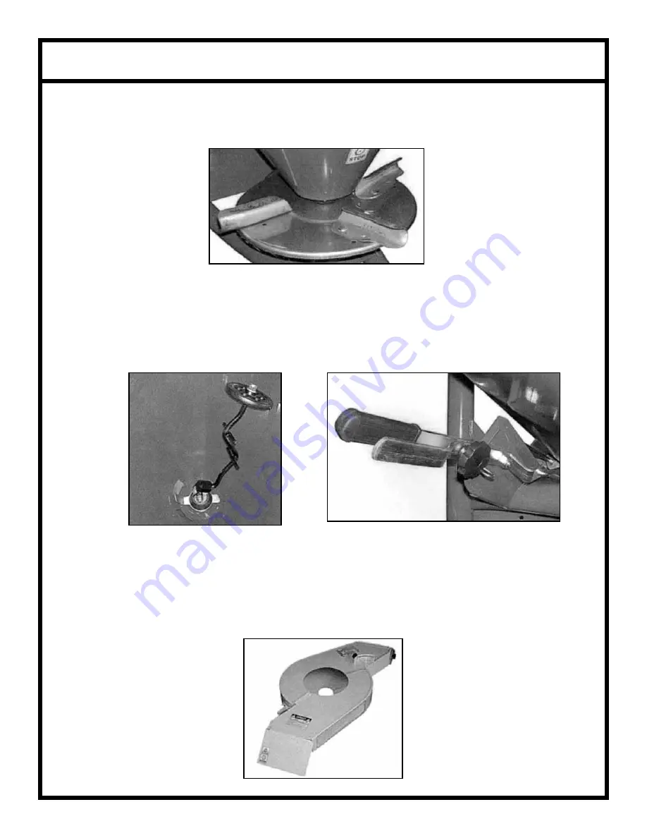
The spreaders are equipped with a stainless steel disc with 4 adjustable vanes in 4 different positions. 
The vanes are bolted in place in the most used position.

The feeding of the disc is by gravity through an opening, located on the bottom of the hopper, inside of 
which a mix/agitator is applied, in order to prevent the fertilizer lumps formation. A sheet case is placed 
in front of the disc, in order to prevent the spreading in the front side of the machine.

If the material you are spreading does not fl ow evenly, a longer optional agitator is available.

If band spreading on rows is required, a one or two row band spreading attachment is available. This 
attachment is easy to bolt up to all models of our 3-point hitch spreaders.

Spreader Disc

Optional Agitator

Lever System

Summary of Contents for PTP180-P

Page 1: ...SEEDER SPREADERS TRAILER MOUNT Assembly Operation Service Parts Manual For Models PTP180 P PTP300 P March 2009 Form PTPSprdr...

Page 2: ...nformation 5 Assembly 6 9 Pull Type Spreader Use 10 Adjusting the Spread 11 Spreading Chart 12 Adjustment 13 Adjusting Spreader Vanes 13 Features Option 14 Lubrication Service 15 Replacement of Spread...

Page 3: ...anics genuine service parts and the necessary tools and equipment to handle all of your service needs Use only genuine service parts Substitute parts will void the warranty and may not meet standards...

Page 4: ...hout incurring any obligation to install them on units previously sold Because of the possibility that some photographs in this manual were taken of prototype models production models may vary in some...

Page 5: ...operation on the machine stop the engine of the tractor or of the self moving means remove the key put on the parking brake and read carefully the operator s manual 2 ATTENTION DANGER Possible throwin...

Page 6: ...r within 25 of machine while in operation DO NOT stop or start suddenly when going uphill or downhill Avoid operation on steep slopes Be alert for holes in terrain and other hidden hazards ALWAYS driv...

Page 7: ...er of every machine a name plate is fixed showing the model the number of series and the year of construction of the machine When some spare parts are required it is always necessary to refer to the t...

Page 8: ...ease zerks as shown STEP 2 Put the washer 25 x 35 x 1 into the right axle STEP 3 Set the right shaft into the bushing as shown STEP 4 Set the left shaft into the bushing STEP 5 Set the gearbox into th...

Page 9: ...th the 4 bolts 10 x 100 and their M10 self locking nuts STEP 9 Set the 5 x 40 pin as shown STEP 10 Lay the frame as shown STEP 11 Set the axle frame on the hopper frame tightening it with the 4 ea 10...

Page 10: ...support brace in place STEP 14 Set the telescopic axle with its 8 x 40 bolt and M8 wing nut as shown STEP 15 very important Set the output shaft into the spreading disc then drive 1 ea 8 x 40 and 1 e...

Page 11: ...TEP Continued STEP 17 Tighten the output shaft as shown STEP 18 Place the PVC hopper in frame and install the 2 opening levers STEP 19 Drill and bolt hopper in place IMPORTANT Make sure the bottom of...

Page 12: ...days in order to improve the uniformity of the distribution CONNECTIONS The pull type spreaders model PTP can be hitched to every type of tractor or ATV quad with a 2 ball To make the connection it is...

Page 13: ...ref I A and B levers must be in the same position connected through grip handle C In order to carry out the spreading only through the left side ref II it is necessary to disconnect the two levers rem...

Page 14: ...SPREADING CHART 12...

Page 15: ...umidity of the fertilizer and on the roughness of the land The fertilizer must always be stored and conserved adequately so as to keep its physical characteristics unchanged HOW TO ADJUST THE SPREADER...

Page 16: ...agitator is applied in order to prevent the fertilizer lumps formation A sheet case is placed in front of the disc in order to prevent the spreading in the front side of the machine If the material yo...

Page 17: ...using them to inject lubricating grease Lubricate with lithium grease the points shown in the picture Point to grease REPLACEMENT OF THE SPREADER VANES In case the spreading vanes of the disc break or...

Page 18: ...fter having hitched the machine to the tractor and having carried out the necessary regulations it is pos sible to begin work ATTENTION Before getting off from the ATV and before every operation of ma...

Page 19: ...that is half of the working width that is used point 1 2 Drive into the field distributing the fertilizer on all the perimeter 3 Stop the tractor at one distance D from the point 1 equivalent to the s...

Page 20: ...PARTS BREAKDOWN 18...

Page 21: ...PARTS BREAKDOWN 19...

Page 22: ...6 1 300 024 Screw TE 12 x 35 UNI 5739 17 1 307 001 Split Pin 4 5 18 1 605 004 Left Shutter 19 1 605 003 Right Shutter 20 1 602 001 Right Tie Rod 21 1 602 002 Left Tie Rod 22 2 303 009 Flat Washer 10 5...

Page 23: ...2 305 015 Dowel M6 89 1 323 013 Output Shaft with Bushing 90 2 300 027 Screw TE 8 x 50 UNI 5737 91 1 301 006 Self Locking Nut M22 92 1 300 021 Screw TE 22 x 80 UNI 5739 93 1 613 030 Tow Tube For 1 Ho...

Page 24: ...rranty does not extend to loss of crops loss because of delay in harvesting or any other expenses for any other reasons Gearmore in no way warranties engines tires or other trade accessories since the...

Reviews: