background image

GEAX  

s.r.l.                             

        Chapter 3                                                                                             


       MAINTENANCE ACCORDING TO THE CONDITIONS OF THE DRILLING M.   

3-10 


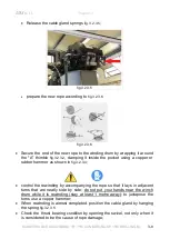
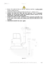
•  release  the  insert  "A" 

fig.3.2.3.2 

which  secures  the  rope  to  the  drum 

fig.3.2.3.3

  Release the cable gland springs 

fig. 3.2.3.5;


prepare the new rope according to 

fig.3.2.3.6 

  Secure  the  end  of  the  new  rope  to  the  winding  drum  by  wrapping  it 

around  the  "A"  thimble 

fig.3.2.3.2

,  clamping  it  inside  the  pocket  using  a 

copper or rubber hammer as shown in 

fig.3.2.3.4


  control  the  rewinding  by  accompanying  the  rope  so  that  it  lays  in 

adjacent turns that are neatly side by side; do not put your hands near 
the winch drum while it is rewinding; stay at least 1 metre away; use a 
copper hammer to juxtapose the turns; 

  when rewinding is almost complete position the  rope gland by hooking 

the springs 

fig.3.2.3.5

  position the rope on the return pulleys and constrain the end of the rope 

fig.3.2.3.7

 to the eyebolt using the special pin; 

  reposition the collar of the limit switch mechanism; 

  reactivate the ascent limit switch of the auxiliary winch 

  position  the  mast  in  work  position  and  test  the  ascent  and  descent  of 

the hook. 

 
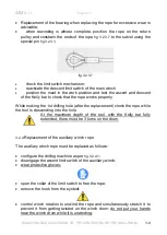
During the 1st lift (after the replacement) check the rope during ascent and 
descent. Check the operation of the limit switch. 


Summary of Contents for XD5

Page 1: ...MAINTENANCE MANUAL Rev 01 17 GEAX s r l XD5...

Page 2: ...Serial number 020J005X GEAX s r l via Campoceraso 13 60027 Osimo AN ITALY Tel 39 0717131953 Fax 39 071715199 www geax it info geax it...

Page 3: ...unit of the machine one must read the XD5 MAINTENANCE MANUAL and only then after having understood the contents one can proceed For operations not described in the manual or if unsure about the meanin...

Page 4: ...ng Improving safety measures is a never ending task should you encounter a potentially dangerous situation that is not adequately covered in this manual please let us know 1 1 4 General summary diagra...

Page 5: ...entions to adapt the drilling machine to special work requirements Interventions to adapt the drilling machine to special work requirements must necessarily be implemented by GEAX s r l Any changes ma...

Page 6: ...ics of the materials change over time regardless of effective operation 2 1 2 Scheduled operations for replacing parts This refers to periodic maintenance operations with the replacement of parts or f...

Page 7: ...RICATION GREASE GREASE TYPE DESCRIPTION TECHNICAL DATA A Agip GR MU 2 Iso DIN 51825 NLGI consistency 2 Manipulated penetration 280 dmm ASTM dropping point 120 C Base oil viscosity at 40 103 mm2 s B Ag...

Page 8: ...post cylinder 2 points 600 A 3 Pull push hydraulic cylinder 2 points 600 A 4 Rotary slewing ring 2points 50 B 5 Rotary gears 2 points 200 B 6 Sliding guides 8 points 50 A every wash with pressure wash...

Page 9: ...ed lubrication operations The lubricant of the winch gear unit must be replaced at a frequency shown in tab 2 2 3 1 2 MAIN WINCH GEAR UNIT LUBRICATION Brevini BWF 2000 LUBRICATION DESCRIPTION Replacem...

Page 10: ...the frequency and methods for checking the ropes Main winch rope inspection Diameter 9 mm Operation Frequency hours Diameter mm Visual inspection with the mast in transport position of the section of...

Page 11: ...e rope and keeping it taught so that it does not touch the ground If one finds worn points measure the diameter it must not fall below more than 7 of the nominal value 200 6 5 If one finds anomalies i...

Page 12: ...ilted of the integrity of the pulleys of the main winch at the beginning of each work shift Inspection with the mast tilted of the integrity of the pulleys of the auxiliary winch at the beginning of e...

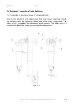
Page 13: ...ightness torque of component bolts Due to the vibrations and adjustments that may cause loosening should periodically check the tightening of the bolts of the main components The table tab 2 4 1 2 sup...

Page 14: ...s SELF LOCKING NUT CLASS 1 Slewing ring fixing bolts outer side Slewing ring fixing bolts inner side 200 No Yes 10 9 2 Main Winch fixing bolts 200 No 10 9 3 Main Winch fixing bolts 200 Yes 10 9 4 Auxi...

Page 15: ...8 958 574 808 969 714 1 004 1 204 840 1 181 1 418 1 050 1 477 1 772 1 146 1 611 1 933 1 429 2 009 2 411 1 549 2 179 2 614 1 941 2 729 3 275 1 997 2 809 3 370 2 497 3 511 4 213 2 584 3 633 4 360 3 242...

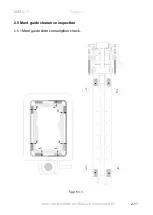
Page 16: ...GEAX s r l Chapter 2 DRILLING MACHINE SCHEDULED MAINTENANCE 2 11 2 5 Mast guide clearance inspection 2 5 1 Mast guide slide consumption check fig 2 5 1 1...

Page 17: ...points 1 2 3 and 4 tab 2 5 1 2 The measurements indicated in tab 2 5 1 2 can be verified using a thickness gauge One must not measure close to the edge where consumption is higher but at a certain de...

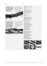
Page 18: ...onditions of the drilling machine 3 2 1 Conditions requiring the replacement of the rope or intensification of inspections While inspecting the rope one must check a the diameter of the rope b the amo...

Page 19: ...GEAX s r l Chapter 3 MAINTENANCE ACCORDING TO THE CONDITIONS OF THE DRILLING M 3 2 cc if cases such as those below occur according to standard ISO 4309 90 the pictures are taken from the Teci manual...

Page 20: ...GEAX s r l Chapter 3 MAINTENANCE ACCORDING TO THE CONDITIONS OF THE DRILLING M 3 3...

Page 21: ...GEAX s r l Chapter 3 MAINTENANCE ACCORDING TO THE CONDITIONS OF THE DRILLING M 3 4...

Page 22: ...GEAX s r l Chapter 3 MAINTENANCE ACCORDING TO THE CONDITIONS OF THE DRILLING M 3 5...

Page 23: ...wire treatment Galvanised cl B Structure Steel hose Manufacturer data typ Teci FAZ A6 D 9 tab 3 1 3 1 The length of the rope refers to a version with standard Kelly bar If the machine has a different...

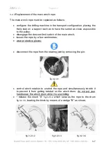
Page 24: ...gage the descent limit switch of the main winch loosen the rope by a few centimetres wear protective gloves disconnect the rope from the rotating joint by removing the pin fig 3 2 3 1 control winch ro...

Page 25: ...pocket using a copper or rubber hammer as shown in fig 3 2 3 4 control the rewinding by accompanying the rope so that it lays in adjacent turns that are neatly side by side do not put your hands near...

Page 26: ...rope works properly While making the 1st drilling hole after the replacement check the rope while the tool is descending into the hole At the maximum depth of the tool with the Kelly bar fully extende...

Page 27: ...adjacent turns that are neatly side by side do not put your hands near the winch drum while it is rewinding stay at least 1 metre away use a copper hammer to juxtapose the turns when rewinding is almo...

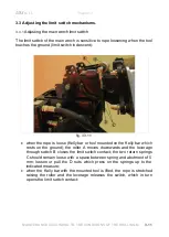
Page 28: ...s loose Kelly bar or tool mounted on the Kelly bar which rests on the ground the roller A moves downwards and the leverage through switch B closes the limit switch contact the two return springs C sho...

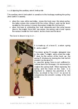
Page 29: ...ht force that overcomes the spring return and opens the contact inside the limit switch via the chain and the lever The lever is shown in fig 3 3 2 1 It is made up of a lever G a return spring E and a...

Page 30: ...B1 in table 1 1 4 1 the following list is not exhaustive 4 2 Replacement of the telescopic kelly bar 4 2 1 Disassembly of the Kelly bar following damage or to change the type To replace the telescopi...

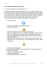
Page 31: ...g out the pin 2 fig 4 2 1 1 and fig 3 2 3 1 remove the kelly bar from the hole and put it in a horizontal position on the ground using the auxiliary winch hook it in the same point as the main winch c...

Page 32: ...sure that the kelly bar is not released position the machine near the hole position the the machine with the mast in the vertical position at maximum height and aligned with the hole in the ground dis...

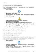
Page 33: ...ssemble it with the engine wear work gloves position the mast in the transport configuration switch the engine off make sure that the hydraulic oil is at room temperature secure the engine gear unit t...

Page 34: ...keep the device stable even when the fixing bolts have been removed main winch 42 kg auxiliary winch 27 kg remove the bolts starting from those in the lowest position rest the winch on a trailer to mo...

Page 35: ...ircuit by loosening the hydraulic pipes downstream the block valve provide a suitable oil collection container at the same time beware of any mast movements fully detach the oil supply pipes protectin...

Page 36: ...after it has been tightened replace the entire pipe complete with fittings with the relative spare part Do not replace the defective fitting only because this involves shortening the pipe length and a...

Page 37: ...functions 4 6 1 Fault detection There may be several malfunctions caused by electric faults and they must be detected properly for malfunctions on devices mounted originally on the crawler one must re...

Page 38: ...2 Faults on the limit switch system 5 2 1 Fault on the main winch limit switch system in descent The malfunction of the limit switch system can be caused both by an unsuitable adjustment of the limit...

Page 39: ...onnector of solenoid valve E13 must switch on connection integrity and solenoid valve E13 must intervene solenoid valve integrity check the control lever of the limit switch as per par 3 3 2 If one co...

Page 40: ...mm real diameter under tension Df 8 mm Phonic wheel teeth 14 K Rope Diam Df mm Pulley Diam Dg mm 7 8 9 169 3 9494 3 9719 3 9943 170 3 9719 3 9943 4 0168 171 3 9943 4 0168 4 0392 172 4 0168 4 0392 4 0...

Page 41: ...m d N N teeth m Rope Diam Df mm Pulley Diam Dg mm 7 8 9 169 25 3 25 2 25 0 170 25 2 25 0 24 9 171 25 0 24 9 24 8 172 24 9 24 8 24 6 173 24 8 24 6 24 5 2 rAtE sel button pag 8 CUB5 manual Sel RAtE Enb...

Reviews: