background image

2

Aeware

®

, Gecko

®

, and their respective logos are Registered Trademarks of Gecko Alliance Group

ingrid™, inye™, inyt™, inyj™, ink1000™, inclear™, intouch 2™, ink110™ and their respective logos are Trademarks of Gecko 

Alliance Group


All other product or company names that may be mentioned in this publication are tradenames, trademarks or registered trademarks 

of their respective owners

Safety instructions


IMPORTANT SAFETY INSTRUCTIONS:


For your own safety please read the following important safety instructions carefully before attempting to 


connect this unit to the mains power supply They will also enable you to get the best performance from and   


prolong the life of the unit:

* READ THESE INSTRUCTIONS

* KEEP THESE INSTRUCTIONS

* HEED ALL WARNINGS

* FOLLOW ALL INSTRUCTIONS

* CLEAN ONLY WITH DRY CLOTH BEWARE THE APPLICATION OF SOME PRODUCTS COMMONLY USED AGAINST 

CORROSION (SUCH AS WD-40 FAMILY PRODUCTS) AS THEY COULD DAMAGE THE ENCLOSURE, DUE TO A NEGATIVE 

CHEMICAL REACTION BETWEEN SOME INDUSTRIAL OILS AND ITS PLASTIC ENCLOSURE ANY OTHER MATERIALS WHICH 

MAY COME IN CONTACT WITH THE ENCLOSURE MUST BE CAREFULLY EVALUATED UNDER END USE CONDITIONS FOR 

COMPATIBILITY

* DO NOT INSTALL NEAR ANY HEAT SOURCES CLEARANCE AND MINIMUM DISTANCE BETWEEN THE VARIOUS PARTS OF 

THE APPLIANCE AND THE SURROUNDING STRUCTURE ARE NOT SPECIFIED AS LONG AS THEY ARE SUFFICIENT SO THAT 

THE AMBIENT TEMPERATURE AROUND THE APPARATUS DOES NOT EXCEED 140°F (60°C)

* ONLY USE ATTACHMENTS/ACCESSORIES SPECIFIED BY THE MANUFACTURER

* UNPLUG THIS APPARATUS DURING LIGHTNING STORMS OR WHEN UNUSED FOR LONG PERIODS OF TIME

* REFER ALL SERVICING TO QUALIFIED SERVICE PERSONNEL SERVICING IS REQUIRED WHEN THE APPARATUS HAS 

BEEN DAMAGED IN ANY WAY, SUCH AS POWER-SUPPLY CORD OR PLUG IS DAMAGED, LIQUID HAS BEEN SPILLED OR 

OBJECTS HAVE FALLEN INTO THE APPARATUS, THE APPARATUS HAS BEEN EXPOSED TO RAIN OR MOISTURE, DOES NOT 

OPERATE NORMALLY, OR HAS BEEN DROPPED

* MUST BE ROUTED AWAY FROM HIGH-VOLTAGE CABLES

CAUTION: 

TO REDUCE THE RISK OF ELECTRIC SHOCK, DO NOT REMOVE SCREWS ON THE BACK OF 

THE ENCLOSURE NO USER-SERVICEABLE PARTS INSIDE REFER SERVICING TO QUALIFIED SERVICE 
PERSONNEL

The lightning flash with the arrowhead symbol within an equilateral triangle is intended to alert the user to 
the presence of uninsulated ‘‘dangerous voltage’’ within the product’s enclosure that may be of sufficient 
magnitude to constitute a risk of electric shock to persons

The exclamation point within an equilateral triangle is intended to alert the user to the presence of important 
operating and maintenance (servicing) instructions in the service literature accompanying this appliance


CAUTION

RISK OF ELECTRIC SHOCK 

DO NOT OPEN

Summary of Contents for 0608-521033

Page 1: ...da 9919 101532 B Rev 11 2017 Groupe Gecko Alliance inc 2017 All trademarks or registered trademarks are the property of their respective owners Select use and synchronize alternative heat sources Bene...

Page 2: ...grid dimensions 6 OEM installation 6 Connections 7 Installation 9 Installation with external heat pump or gas heater 9 Installation with a heat exchange unit 10 Heat Mode Operations 11 in k110 and Acc...

Page 3: ...N THE VARIOUS PARTS OF THE APPLIANCE AND THE SURROUNDING STRUCTURE ARE NOT SPECIFIED AS LONG AS THEY ARE SUFFICIENT SO THAT THE AMBIENT TEMPERATURE AROUND THE APPARATUS DOES NOT EXCEED 140 F 60 C ONLY...

Page 4: ...VICING OR MODIFYING ANY CABLE CONNECTIONS IN THIS UNIT IN GRID ENCLOSURE SHALL BE LOCATED ABOVE THE FLOOD ZONE WHERE IT S UNLIKELY TO BE SUBMERGED IN THE EVENT THE SPA IS OVERFILLED OR SIMILAR ABNORMA...

Page 5: ......

Page 6: ...ng sources Connected to the CO port of your spa control system in grid will act as a dispatcher of external heating sources such as your heat pump or your central house heating system With in grid you...

Page 7: ...s unit is connected to an in ye or a in yt spa control system We recommend that you install the unit with 8 pan head screws The unit must be installed in an upright position as illustrated Fastening b...

Page 8: ...te properly in grid connection with accessories If you have a lot of accessories the in link cable of the in grid with 4 single button switches and a CO port can also be connected to any CO port of an...

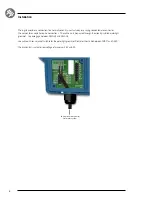
Page 9: ...ections The cable must be passed through the already installed watertight grommet Use wire gage between AWG 24 and AWG 16 Use cable with round jacket suitable for the watertight grommet Diameter shoul...

Page 10: ...a control system heater as illustrated above The unit must be installed after your spa control system as illustrated above You need to be sure your pump heater or gas heater is set to the maximum set...

Page 11: ...your Y series spa control system needs a minimum of 20 GPM all the time Make sure to always connect your heat exchange unit in the same water pipe filter of your Y series spa control system heater The...

Page 12: ...l be closed if the external heating system is activated Otherwise the relay contacts are open Your desired heat mode must be set by adding a jumper on one of the five 5 different positions Note Your h...

Page 13: ...it will be easier to set your preferred heating mode back once the external heating system is available 3 EXT External Use this mode for a maximum energy saving purpose The spa control system will onl...

Page 14: ...the in grid 5 SMART Energy savings Use this mode for a better energy saving purpose combined with a maximum water temperature regulation efficiency The spa control system will always use the external...

Page 15: ...output connectors available at the front The AC jumper line goes from top to bottom and the AC connector line goes from left to right e g If your first jumper on your AC selector line is P2 it will b...

Page 16: ...e Accessory AC jumper Settings AC 1 P1 AC 2 P2 AC 3 LST AC 4 L Heat Mode SMART Accessory AC jumper Settings AC 1 P1 AC 2 P2 AC 3 P3 AC 4 P4 AC 5 P5 Heat Mode DIS Disable in grid 4 AC and CO model Part...

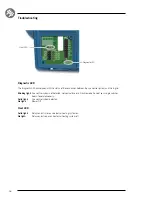
Page 17: ...nking light Spa control system not detected not compatible or in Disable mode if one of your single switches doesn t operate properly Solid light Spa control system detected No light Power Off Diagnos...

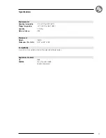
Page 18: ...to 185 F 85 C Humidity 70 Max Water resistance IPX5 Mechanical Weight 0 85 lb Dimensions W x H x D 5 50 x 4 48 x 1 84 Compatibility in ye and in yt spa control systems with appropriate software revisi...

Page 19: ...da 9919 101532 B Rev 11 2017 Groupe Gecko Alliance inc 2017 All trademarks or registered trademarks are the property of their respective owners Select use and synchronize alternative heat sources Bene...

Reviews: