background image

Deutsch

Page XX

Page XX

LH600

PANTONE 431C
C 45 M27 Y17 K51

PANTONE 297C
C 51 M0 Y1 K0

Summary of Contents for Loop Hear LH600

Page 1: ...LH600 ...

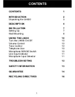
Page 2: ...ing Up 7 Wall Mounting 8 USING THE LH600 10 Turn the LH600 On Off 10 Volume Control 10 Tone Control 10 Telephone Use 10 Microphone SENSE Switch 10 Line Input Selector 11 Microphone Input Selector 11 TROUBLESHOOTING 12 SAFETY INFORMATION 13 GUARANTEE 14 RECYCLING DIRECTIVES 16 CONTENTS ...

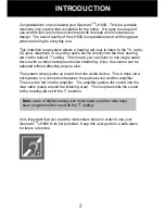
Page 3: ...ngle audio device with no other background noise interfering Also the volume can be adjusted without affecting anyone else The system simply picks up sound from the audio device This is done via a microphone or a connection between the audio device and the amplifier The sound is fed into the amplifier The amplifier passes the sound into the loop cable setup around the listening area This loop tran...

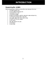
Page 4: ...Power adaptor charging Unit 1 Telephone line cord 1 Telephone adaptor 1 External microphone with 3m extension lead and lapel clip 1 3 5mm stereo jack to RCA convertor 1 2m audio cable with 3 5mm stereo plug 1 SCART to RCA jack adaptor 1 Loop Cable 100 cable clips for the wall 1 Wall Mount 1 User Guide INTRODUCTION ...

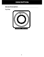
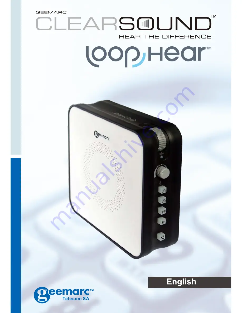
Page 5: ...4 General Description Top View DESCRIPTION ...

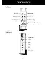
Page 6: ...5 Left View Right View DESCRIPTION Volume Power LED Tone MIC 1 MIC 2 Line 1 Line 2 MIC sense Mic input 2 Mic input 1 Audio input 1 Audio input 2 Telephone input 1V DC supply Connections for cable loop ...

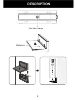
Page 7: ...6 Wall Mount Hanger Wall Mount DESCRIPTION ...

Page 8: ...ect the RCA convertor cable to the TV set connect the 3 5mm stereo cable to the RCA convertor cable connect the other end of the 3 5mm stereo cable to the unit stereo jack of LINE 1 For a TV with 3 5mm stereo jack audio output connect the 3 5mm stereo cable to the TV set connect the other end of the 3 5mm stereo cable to the unit stereo jack of LINE1 If you have another audio device you wish to co...

Page 9: ...n each nail clip Any excess loop wire can either be cut or tied up The minimum length of loop wire is 10meters Insert the two ends of the wire into speaker clip terminals of the unit Ensure that only bare wire and not the plastic insulation is inserted Connect the Power Supply Connect the plug of the supplied power adaptor into the DC jack Plug the other end of AC power adaptor into the mains wall...

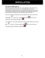
Page 10: ...or someone to speak directly into the loop system whilst the hearing aid user is listening to a sound source Connect the external microphone wire provided into the 2 5mm stereo jack marked MIC1 on the unit Push the button MIC1 to turn on the microphone the indicator will light red If you want to use a second microphone use the 2 5mm stereo jack marked MIC2 on the unit Push the button MIC2 to turn ...

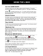
Page 11: ...e When an incoming call is received the ring signal will be added to the loop output and a ringing sound will be heard The audio and microphone input will be muted for 10 seconds The audio source will resume automatically after 10 seconds Microphone SENSE Switch You can select the SENSE switch to select the microphone gain If you press the SENSE switch the red LED will glow red and the microphone ...

Page 12: ...selection switches allow you to fick between two different microphone sources Select MIC1 or MIC2 depending on which source you require Alternatively you can use both input sources at the same time simply press both MIC1 and MIC2 USING THE LH600 ...

Page 13: ... sound source Check the loop cable is wired correctly The sound produced is very loud Turn the audio device volume lower Turn the LH600 volume lower Move the microphone away from the sound source There is a buzz in the background Turn the LH600 off If the buzz persists this is interference from other electrical items However if the buzz disappears on turning the LH600 off there might be a fault wi...

Page 14: ...ld damage the finish or the electronics inside Environmental Do not expose to direct sunlight Always ensure there is a free flow of air over the surfaces of the LH600 Do not place any part of your product in water and do not use it in damp or humid conditions e g bathrooms Do not expose your product to fire or other hazardous conditions SAFETY INFORMATION ...

Page 15: ... not an authorised GeemarcTM representative The GeemarcTM guarantee in no way limits your legal rights IMPORTANT YOUR RECEIPT IS PART OF YOUR GUARANTEE AND MUST BE RETAINED AND PRODUCED IN THE EVENT OF A WARRANTY CLAIM DECLARATION GeemarcTM Telecom SA hereby declares that this product is in compliance with the essential requirements and other relevant provisions of the Radio and Telecommunications...

Page 16: ...15 Electrical connection The apparatus is designed to operate from a 230V 50Hz supply only Classified as hazardous voltage according to EN60950 standard GUARANTEE ...

Page 17: ... the following disposal options Remove the batteries and deposit them in an appropriate WEEE skip Deposit the product in an appropriate WEEE skip Or hand the old product to the retailer If you purchase a new one they should accept it Thus if you respect these instructions you ensure human health and environmental protection For product support and help visit our website at www geemarc com Telephon...

Page 18: ...Hertfordshire AL7 1SB For product support 01707 384438 www geemarc com Parc de l Etoile 2 rue Galilée BP20061 59791 GRANDE SYNTHE CEDEX TEL SERVICE APRES VENTE 03 28 58 75 99 www geemarc com www geemarc com Siemensstrasse 10 53121 Bonn Germany Tel 49 0 228 74 87 09 0 Fax 49 0 228 74 87 09 20 ...

Reviews: