background image

14

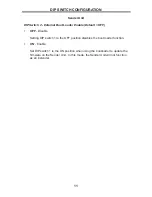
DIP SWITCH CONFIGURATION

Receiver Unit

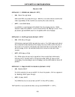
DIP Switch 4 - Green Mode (Default = OFF)

• OFF

 - Enable Green Mode

When DIP switch 1 on the Receiver Unit is set to the OFF position, the 
Receiver Unit is placed in Green Mode.  In this mode, the unit is not powered 
5V is detected on pin 18 of the HDMI cable.  Green Mode consumes 
less than 1 Watt of power.

• ON

 - Disable Green Mode

If DIP switch 1 is set to the ON position, then the Sender Unit is always 
powered.

DIP Switch 5 - External Boot Loader Enable (Default = OFF)

• OFF

 - Disable

Setting DIP switch 1 to the OFF position disables the boot loader function.

• ON

 - Enable

Set DIP switch 1 to the ON position when using the bootloader to update 
the fi rmware on the Receiver Unit.  In this mode, the Receiver Unit will not 
function as an Extender.

DIP Switch 6 - Not Used

• 

Reserved for future expansion.

Both the Sender Unit and Receiver Unit must be placed in Green 
Mode in order to use the Green Mode feature.

Summary of Contents for GEF-HDCAT5-ELRPOL2

Page 1: ...1080P Extender for HDMI ELR with PoL 2 over CAT5 GEF HDCAT5 ELRPOL2 User Manual www gefenpro com...

Page 2: ...h CA 91311 www gefenpro com support gefenpro com Notice Gefen LLC reserves the right to make changes in the hardware packaging and any accompanying documentation without prior written notice Extender...

Page 3: ...escriptions 6 Receiver Unit Layout 7 Receiver Unit Descriptions 8 Connecting the Extender for HDMI ELR PoL 2 over CAT5 9 Wiring Diagram 10 DIP Switch Configuration 10 Sender Unit 12 Receiver Unit 15 N...

Page 4: ...meters using one CAT 5 cable In addition Gefen s PoL technology gives it the capability to power an additional 5V DC device up to 2 Amps at the Receiver unit over the CAT 5 cable The Extender for HDM...

Page 5: ...mended to safeguard against random video flashes caused by electromagnetic interference EMI The Extender for HDMI ELR with PoL 2 over CAT5 features the ability to generate compatible EDID and Hot Plug...

Page 6: ...urce switching between Sender Unit source and Receiver Unit source Fully HDMI and HDCP compliant EDID management for rapid integration of source and display devices Built in IR Blaster allows IR remot...

Page 7: ...4 SENDER UNIT LAYOUT Back Front 1 2 3 5 6 6 7 8 4...

Page 8: ...spare 4 Power Switch Turn the power ON or OFF using this switch 5 IR Blaster Connect an IR Blaster cable Gefen part no EXT 2IREMIT from this port to the Hi Def source to control the source from the v...

Page 9: ...6 RECEIVER UNIT LAYOUT Back Front 1 2 3 4 5 6 7 8 9 10 11...

Page 10: ...DC Out Connect an optional locking Gefen part no CAB PWR 06LL or non locking Gefen Part no CAB PWR 06NL power cord to this the included 5 V DC locking power supply connector to power additional devic...

Page 11: ...ce router to the Ethernet input port on the Sender unit using a CAT 5 CAT 5e or CAT 6 cable Connect the Ethernet output port on the Receiver Unit to the remote device router with a CAT 5 CAT 5e or CAT...

Page 12: ...XTENDER FOR HDMI ELR WITH POL 2 OVER CAT5 GEF HDCAT5 ELRPOL2 CAT5 LINK CABLE Up to 330 ft ETHERNET CABLE HDMI CABLE Sender 100BASE T Router 100BASE T Router Set top Box HDMI Display Local HDMI Input S...

Page 13: ...Sender Unt is set to the OFF position the Sender Unit is placed in Green Mode In this mode the unit is not powered unless 5V is detected on pin 18 of the HDMI cable Green Mode consumes less than 1 Wat...

Page 14: ...le Default OFF OFF Disable Setting DIP switch 1 to the OFF position disables the boot loader function ON Enable Set DIP switch 1 to the ON position when using the bootloader to update the firmware on...

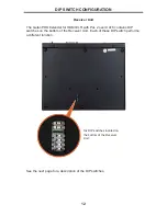
Page 15: ...for HDMI ELR with PoL 2 over CAT5 contains DIP switches on the bottom of the Receiver Unit Each of these DIP switch performs a different function See the next page for a description of the DIP switch...

Page 16: ...flect the connection status between the display device and the source device If the source or monitor is temporarily disconnected then reconnected there will be a delay of 20 30 seconds before the con...

Page 17: ...e If DIP switch 1 is set to the ON position then the Sender Unit is always powered DIP Switch 5 External Boot Loader Enable Default OFF OFF Disable Setting DIP switch 1 to the OFF position disables th...

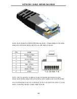
Page 18: ...products Pin Color 1 Orange White 2 Orange 3 Green White 4 Blue 5 Blue White 6 Green 7 Brown White 8 Brown CAT 5 CAT 5e and CAT 6 cabling comes in stranded and solid core types Gefen recommends using...

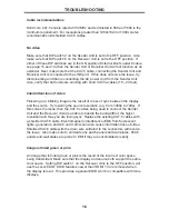
Page 19: ...s of sync between the display and the source Try lowering the source resolution e g from 1080p to 720p If this solves the issue then the CAT 5 cables being used to connect the Sender Unit and the Rece...

Page 20: ...designation is EIA TIA 568 Cat 5 cable typically has three twists per inch of each twisted pair of 24 gauge copper wires within the cable CAT 5e Similar to Cat 5 cable but is enhanced to support spee...

Page 21: ...but DTS competes with Dolby on DVD and in the movie theaters DVI The acronym for Digital Visual Interface DVI is the connection standard developed by Intel for connecting computers to digital monitors...

Page 22: ...ompressed all digital audio video interface HDMI provides an interface between any compatible digital audio video source such as a set top box DVD player and A V receiver and a compatible digital audi...

Page 23: ...Windows based PCs as well IR remote A type of wireless transmission using infrared light waves KVM An acronym for Keyboard Video Mouse A KVM switch is a hardware device that allows control of multiple...

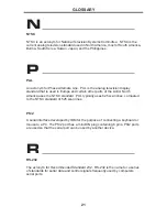
Page 24: ...her parts of the world North America uses the NTSC standard PAL typically uses 625 scan lines compared to the NTSC standard of 525 scan lines PS 2 A serial interface developed by IBM for the purpose o...

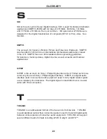
Page 25: ...ines for television motion pictures digital cinema as well as audio and medical applications S PDIF S PDIF is the acronym for Sony Philips Digital Interconnect Format but is more commonly known as Son...

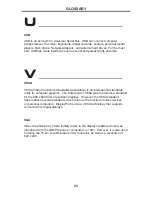
Page 26: ...ds entity for computer graphics The initial goal of VESA was to produce a standard for the 800 x 600 SVGA resolution displays However the VESA standard has produced several standards which relate to t...

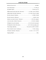
Page 27: ...B 9 female RS 232 Connector Receiver 1 DB 9 male Ethernet Connector Sender Receiver 1 RJ 45 shielded Link Connectors Sender Receiver 1 RJ 45 shielded IR Blaster connector Sender 1 3 5 mm mini mono jac...

Page 28: ...d 1 Proof of sale may be required in order to claim warranty 2 Customers outside the US are responsible for shipping charges to and from Gefen 3 Copper cables are limited to a 30 day warranty and cabl...

Page 29: ...Rev A2 Pb 20600 Nordhoff St Chatsworth CA 91311 1 800 545 6900 818 772 9100 fax 818 772 9120 www gefenpro com support gefenpro com...

Reviews: