background image

page | 37

RS-232 Commands

Advanced Operation

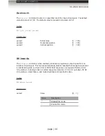
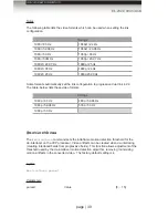
#insel

The 

#insel

 command switches between the HDMI input and the DVI input.

Syntax

:

#key param1

Parameters

:

param1  


Value


Value

Description

0

DVI In

1

HDMI In

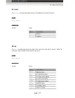
#key

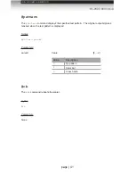
The 

#key

 command emulates the same control used on the IR remote control.  Either the 

full word or the first letter of the word can be used.

Syntax

:

#key param1

Parameters

:

param1  


String


Value

Description

menu

MENU button

up

(Up arrow button)

down

(Down arrow button)

left

(Left arrow button)

right

(Right arrow button)

enter

ENTER button

source

SOURCE button

output

OUTPUT button

Summary of Contents for GEF-HDVI-2-3GSDIS

Page 1: ...Audio Embedder 3GSDI Release A2 User Manual GEF HDVI 2 3GSDIS HDMI and DVI to 3GSDI Scaler...

Page 2: ...t where they exit from the apparatus 11 Only use attachments accessories specified by the manufacturer 12 To reduce the risk of electric shock and or damage to this product never handle or touch this...

Page 3: ...ssly disclaimed 1 Proof of sale may be required in order to claim warranty 2 Customers outside the US are responsible for shipping charges to and from Gefen 3 Copper cables are limited to a 30 day war...

Page 4: ...duct for the support number HDMI and DVI to 3GSDI Scaler is a trademark of Gefen LLC Important Notice Gefen LLC reserves the right to make changes in the hardware packaging and any accompanying docume...

Page 5: ...aler Use the included IR remote control unit to access the OSD The IR channel for both the scaler and the IR remote control unit must be the same in order for the IR remote control unit to control the...

Page 6: ...hatch patterns Four aspect ratio modes Full Screen Panoramic Letter Pillar Extract Crop Film Mode produces a progressively scanned output image from an interlaced scanned input image Serial RS 232 con...

Page 7: ......

Page 8: ...perating the HDMI and DVI to 3GSDI Scaler The On Screen Display 10 Accessing the On Screen Display 10 Moving Around in the OSD 11 General Menu 12 Patterns Menu 13 Output Menu 14 Input Menu 16 Picture...

Page 9: ......

Page 10: ......

Page 11: ...Getting Started Panel Layout 2 Front Panel 2 Back Panel 3 IR Remote Control Unit 4 Front 4 Back 5 Installing the Battery 6 Setting the IR Channel 6 Installation 7 Connecting the HDMI and DVI to 3GSDI...

Page 12: ...trol unit 2 Input Select Press this button to switch between the DVI In and HDMI In inputs 3 HDMI This LED glows bright green when HDMI In is selected 4 3GSDI This LED glows bright green when outputti...

Page 13: ...this connector to the HDMI source 6 3GSDI Out A Out B Connect the scaler to the 3GSDI destination using BNC type cables 7 RS 232 Connect an RS 232 cable from this port to an RS 232 control device Thi...

Page 14: ...features in the On Screen Display See Accessing the On Screen Display for details 3 MENU Displays hides the On Screen Display 4 SOURCE Press this button to toggle between HDMI In and DVI In 5 OUTPUT...

Page 15: ...et the IR channel of the remote See Setting the IR Channel for details 2 Primary battery slot shown without battery Holds the battery for operating the remote Use only 3V CR2032 type batteries Make su...

Page 16: ...emote control to communicate with the HDMI and DVI to 3GSDI Scaler the IR remote control must be set to the same channel as the scaler Use the remotechan command to set the IR channel of the scaler Ge...

Page 17: ...NC type cable from the 3GSDI Out connector s to the 3GSDI destination 6 Connect the included AC power cord from the power supply to an available electrical outlet Sample Wiring Diagram WARNING This pr...

Page 18: ......

Page 19: ...rating the HDMI and DVI to 3GSDI Scaler The On Screen Display 10 Accessing the On Screen Display 10 Moving Around in the OSD 11 General Menu 12 Patterns Menu 13 Output Menu 14 Input Menu 16 Picture Me...

Page 20: ...he front panel of the scaler and press the MENU button Press the MENU button again to dismiss the OSD The OSD contains seven menu buttons each of which contains one or more set of functions for contro...

Page 21: ...W buttons to access each feature within the menu Most of the submenus have an symbol indicating that there are additional options If one of these menus is selected it will automatically be expanded t...

Page 22: ...anguage and press the ENTER key Options Description English Sets the OSD in English default French Localizes the OSD in French General Save Configuration Saves the current configuration of the scaler...

Page 23: ...ption press the ENTER button to enable disable the color bar pattern When the color bar pattern is enabled no video output will be displayed Patterns Cross Hatch Produces a color bar pattern similar t...

Page 24: ...k configuration in respect to color space When using dual link SDI or HD SDI input YCbCr or RGB can be selected By default the Single Link YCbCr 4 2 2 SD HD 3G option will be used When using 3GSDI sig...

Page 25: ...automatic genlock mode Options Description Off Disables Genlock Video Input Use video input as reference clock Ref Input Use clock attached to Ref In Output Genlock Offset This option provides the opt...

Page 26: ...ct which automatically senses the resolution and timing of the input signal The available resolutions under this menu are in SD and HD format Input Input Graphic Format Selects the resolution and timi...

Page 27: ...his feature automatically detects repeated field sequences present in interlaced signals such as 50 Hz or 60 Hz field sequences no repeated fields 60 Hz 3 2 pull down including broken or edited sequen...

Page 28: ...Input Color Range The RGB output color range may be changed set to limited 16 235 or to full 0 255 Options Description Auto Use color range of input signal 16 235 Compress Color range of input signal...

Page 29: ...ange 0 255 RGB Y Output Offset Range 0 1023 Options Description Contrast Red Adjust contrast of red color component Contrast Green Adjusts contrast of green color component Contrast Blue Adjusts contr...

Page 30: ...progressive or interlaced format Changes to the detail enhancement are implemented at the start of the next frame of video Both of these parameters can be adjusted within the range or 0 100 Options D...

Page 31: ...the image Note that this option is not available in the panoramic aspect mode Options Description Horizontal Size Sets horizontal size of the output signal Vertical Size Sets vertical size of the out...

Page 32: ...nd DVI to 3GSDI Scaler Aspect Menu Aspect Full Screen Stretches the output signal to fill the display Aspect Letter Pillar Box Sets the aspect ratio to fit a letter or pillar box format Aspect Panoram...

Page 33: ...a sub window that is always centered on the screen The position is the relative position of the window within the full picture This feature allow you to display one selected section of the input pict...

Page 34: ......

Page 35: ...page 25 HDMI and DVI to 3GSDI Scaler 03 Advanced Operation RS 232 Configuration 26 RS 232 Interface 26 RS 232 Settings 26 RS 232 Commands 27...

Page 36: ...ow control None IMPORTANT When sending RS 232 commands a carriage return must be included at the end of the command A space must be included between the command and each parameter DA 15 DE 9 DB 25 DC...

Page 37: ...isables film mode gamma Sets the gamma correction mode genoffset Sets the genlock offset input Sets the input timing for the source signal insel Switches between HDMI and DVI inputs key Used to emulat...

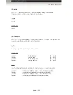
Page 38: ...l Syntax aspect param1 Parameters param1 Aspect ratio 1 5 Value Description 1 Full screen 2 Letter Pillar box 3 Panoramic 4 Extract 5 Through Notes If the Extract or Through mode is selected the defau...

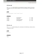
Page 39: ...able Syntax autolock param1 Parameters param1 Aspect ratio 0 1 Value Description 0 Disable 1 Enable blacklev The blacklev command sets the black level of the output signal This is the equivalent of ad...

Page 40: ...eanaper The cleanaper command allows adjustment of the input signal position Each parameter allows an area within the production aperture to be defined The minimum clean aperture size is 0 pixels by 0...

Page 41: ...The default setting for param1 is 0 Syntax colrange param1 Parameters param1 Color range 0 1 Value Description 0 Limited 16 235 1 Full 0 255 contrast The contrast command sets the contrast level for t...

Page 42: ...ate program when updating the firmware but can be executed for any reason Syntax enhance param1 Parameters None Example devtype DEVTYPE HDMITO3GSDI deversion The deversion command displays the current...

Page 43: ...am2 Parameters param1 Value 0 2 Value Description 0 Uses default EDID 1 Upload EDID file 128 bytes 2 Upload EDID file 256 bytes param2 Value 0 2 Value Description 0 EDID address 0 1 EDID address 1 2 E...

Page 44: ...filmmode The filmmode command when enabled produces a progressive output signal from an interlaced input signal This feature automatically detects repeated field sequences present in interlaced signa...

Page 45: ...s If the Custom mode is used then set the gamma coefficient value in the second parameter If User Table is used then set param2 1 to use the table currently saved in the EEPROM To write a new gamma LU...

Page 46: ...0 Syntax genoffset param1 param2 Parameters param1 Output lines Vertical output resolution param2 Output pixels Horizontal output resolution input The input command sets the input timing for the sour...

Page 47: ...HDMI In key The key command emulates the same control used on the IR remote control Either the full word or the first letter of the word can be used Syntax key param1 Parameters param1 String Value D...

Page 48: ...am1 Language 0 1 Value Description 0 English 1 French linkconf The linkconf command sets the link configuration The link configuration is set on the input This feature is not valid for all formats Syn...

Page 49: ...ve dual link 4 2 2 The table below lists these video formats Timings 1080p 60 Hz 480p 59 94 Hz 1080p 59 94 Hz 576p 50 Hz 1080p 50 Hz motionthres The motionthres command sets the intraframe motion dete...

Page 50: ...es The noisethres command sets the noise threshold Syntax noisethres param1 Parameters param1 Value 0 100 output The output command sets the resolution of the output signal See Supported Video and Gra...

Page 51: ...plays the specified test pattern The original output signal is masked when the test pattern is displayed Syntax pattern param1 Parameters param1 Value 0 2 Value Description 0 No pattern 1 Color bar 2...

Page 52: ...h the IR channel of the included IR remote control unit See Setting the IR Channel for instructions on setting the IR channel on the IR remote control unit Syntax remotechan param1 Parameters param1 I...

Page 53: ...is set to Panoramic Syntax sizepos param1 param2 param3 param4 Parameters param1 Horizontal size 1 max param2 Vertical size 1 max param3 Horizontal position 0 max param4 Vertical position 0 max Notes...

Page 54: ...to the size and position of the original output signal Syntax through param1 param2 param3 param4 Parameters param1 Horizontal size 1 100 param2 Vertical size 1 100 param3 Horizontal position 0 100 p...

Page 55: ......

Page 56: ......

Page 57: ...HDMI and DVI to 3GSDI Scaler 04 Appendix Supported Video and Graphic Formats 48 Gamma Look up Table 50 Mounting Plate Installation 51 Fuse Replacement 52 Firmware Update Procedure 54 Specifications 55...

Page 58: ...45 720p 30 Hz 11 1024 x 768 85 Hz 46 720p 50 Hz 10 1280 x 854 65 720p 59 94 Hz 9 1152 x 864 75 Hz 47 720p 60 Hz 8 1280 x 768 60 Hz 48 1035i 59 94 Hz 64 1280 x 960 60 Hz 49 1035i 60 Hz 63 1280 x 960 85...

Page 59: ...15 2K p 24 Hz 76 720p 50 Hz 14 2K sf 23 98 Hz 73 720p 25 Hz 13 2K sf 24 Hz 74 720p 29 97 Hz 12 720p 30 Hz 11 720p 50 Hz 10 720p 59 94 Hz 9 720p 60 Hz 8 1035i 59 94 Hz 64 1035i 60 Hz 63 1080i 50 Hz 24...

Page 60: ...e file as UpdateGamma bat Make sure that the GefenUpdater exe file resides in the same directory or is in the path as the UpdateGamma bat file 4 Connect a USB cable from the computer to the HDMI and D...

Page 61: ...installation of this unit into a 1U rack mount space 1 Locate the side screws on the unit 2 Remove the front 2 screws that are located closest to the front of the unit 3 Using the removed screws screw...

Page 62: ...EC connector on the scaler 2 Locate the fuse door between the IEC connect and the power switch on the back of the unit 3 Use a small flat head screwdriver to gently pry the locking mechanism on the fu...

Page 63: ...es not lock into place the fuse may not be centered in the C cradle In this case rotate the scaler on its side and reinstall the fuse drawer This will allow the fuse to stay centered as the fuse drawe...

Page 64: ...pen the Updater ini file located in the firmware files folder 5 Locate the Setup section within the Updater ini file 6 Change the COM port setting to the virtual COM port Example Setup comport COM5 If...

Page 65: ...30 Hz 576p 720p 1035i 1080i 1080p 50 Hz 480p 720p 1035i 1080i 1080p 59 94 Hz 1080i 1080p 50M Hz 720p 1080i 1080p 60 Hz Output Video Bandwidth 3 0 Gbps max Electrical Maximum Pixel Clock 225 MHz Power...

Page 66: ...Appendix Specifications Operational Power Input 100 240V AC 50 60 Hz Power Consumption 20W max Physical Dimensions W x H x D 17 x 1 73 x 7 7 432mm x 44mm x 195mm Unit Weight 3 lbs 1 4 kg...

Page 67: ......

Page 68: ...dhoff St Chatsworth CA 91311 1 800 545 6900 818 772 9100 fax 818 772 9120 www gefenpro com support gefenpro com Pb Stretch it Switch it Split it Gefen s got it This product uses UL or CE listed power...

Reviews: