background image

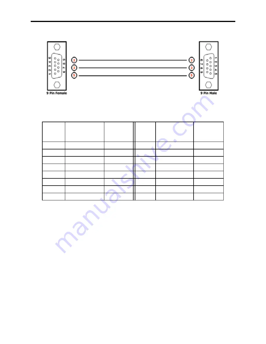
RS-232 INTERFACE

8

Binary Table

ASCII Corresponding 

RMT16-IR

Button

Binary

ASCII Corresponding

RMT16-IR

Button

Binary

1

1

0011 0001

9

9

0011 1001

2

2

0011 0010

a

10

0110 0001

3

3

0011 0011

b

11

0110 0010

4

4

0011 0100

c

12

0110 0011

5

5

0011 0101

d

13

0110 0100

6

6

0011 0110

e

14

0110 0101

7

7

0011 0111

f

15

0110 0110

8

8

0011 1000

g

16

0110 0111

RS232 Settings

Bits per second ....................................................................................... 19200  

Data bits .......................................................................................................... 8

Parity ........................................................................................................ None

Stop bits ...........................................................................................................1

Flow Control ............................................................................................. None

Summary of Contents for DVI-444N

Page 1: ...4x4 DVI Matrix U S E R M A N U A L www gefen com ...

Page 2: ...en Inc c o Customer Service 20600 Nordhoff Street Chatsworth CA 91311 www gefen com support gefen com Notice Gefen Inc reserves the right to make changes in the hardware packaging and any accompanying documentation without prior written notice The 4x4 DVI Matrix is a trademark of Gefen Inc 2007 Gefen Inc All Rights Reserved ASKING FOR ASSISTANCE ...

Page 3: ...res Panel Layout Using the 4x4 DVI Matrix RMT16 IR Installation IR Codes Dip Switch Guidelines RS 232 Interface 4x4 DVI Matrix Rack Mount Diagram Specifications Terminology Troubleshooting Troubleshooting Diagram Warranty 1 2 3 4 5 6 7 8 9 10 11 12 13 14 ...

Page 4: ...s to DVI input 3 The DVI port of DVI source 4 connects to DVI input 4 There are four 4 DVI outputs connecting to four 4 different displays Note The switching is done by using either the RMT 16 IR remote control or through the RS232 port The 4x4 DVI Matrix is rack mountable 1 OPERATION NOTES READ THESE NOTES BEFORE INSTALLING OR OPERATING THE 4x4 DVI Matrix The 4x4 DVI Matrix is housed in a metal b...

Page 5: ...p to 1080p 2K and 1920x1200 Maintains highest DVI single link video resolution DVI or HDMI to DVI cables are used to connect the inputs and outputs of the matrix Each display s inputs can be switched with the IR remote control or through RS232 Includes 1 4x4 DVI Matrix 4 DVI 6ft Male to Male Cables 1 5VDC Power Supply 1 User Manual 1 RMT 16IR Remote Control 1 Rack Ears ...

Page 6: ...D Indicator Front Panel RS232 Controller Port Display 2 LED Indicator Display 3 LED Indicator Display 4 LED Indicator IR Sensor IR Extender Eye Port Power Indicator Back Panel Connects to 5VDC Power Supply DVI Inputs DVI Outputs ...

Page 7: ...computer boots up it looks for an EDID extended display identification data from the display to tell it what monitor is connected and what resolution to output Dur ing boot up of the computer you should have ONLY one output selected to one input at a time so that the computer gets the EDID of the display that is selected If you have multiple outputs selected to one computer the computer will read ...

Page 8: ...rked must be facing down 4 Test the RMT16 IR remote by pressing ONLY one button at a time The indicator light on the remote will flash once each time you press a button WARNING Do not press multiple buttons simultaneously and do NOT press buttons rapidly These actions will cause the remote to reset and steps 1 4 will have to be repeated Note The RMT16 IR ships with two batteries One battery is req...

Page 9: ... on the RMT16 IR to any of the combinations pic tured below 4 Dip Switches 1 and 2 in the RMT16 IR correspond with Dip Switches 1 and 2 inside the 4x4 DVI Matrix respectively Switch the switches inside the 4x4 DVI Matrix to match the same Remote Channel as the RMT16 IR The 4x4 DVI Matrix is now set to a new IR Code 1 2 Remote Channel 0 1 2 Remote Channel 1 1 2 Remote Channel 2 1 2 Remote Channel 3...

Page 10: ...n RMT 16 IR 3 Unused Unused 4 Unused Unused 5 Unused Unused 6 Unused Unused 7 Unused Unused 8 Unused Unused Underneath the 4x4 DVI Matrix are two banks of Dip Switches Below is a table describing their functions By default the Bank of 8 switches are set of to the Off position and the other bank of 4 switches are set to ON The bank of 4 dip switches are service switches and should not be changed fr...

Page 11: ... 1 0011 0001 9 9 0011 1001 2 2 0011 0010 a 10 0110 0001 3 3 0011 0011 b 11 0110 0010 4 4 0011 0100 c 12 0110 0011 5 5 0011 0101 d 13 0110 0100 6 6 0011 0110 e 14 0110 0101 7 7 0011 0111 f 15 0110 0110 8 8 0011 1000 g 16 0110 0111 RS232 Settings Bits per second 19200 Data bits 8 Parity None Stop bits 1 Flow Control None ...

Page 12: ...4x4 DVI MATRIX RACK MOUNT DIAGRAM 9 ...

Page 13: ...C Signal 5 volts p p TTL DVI Connector DVI I 29 pin female digital only Single Link Range 1080p 1920 x 1200 Remote Control Port RS 232 Female Mini Stereo Power Consumption 30 watts max Power Supply 5V DC Dimensions 17 W x 1 75 H x 5 875 D Shipping Weight 10 lbs SPECIFICATIONS 10 ...

Page 14: ...ise can be described as snow or brightly colored pixels that are sometimes referred to as sparkles To switch auto equalization off look on the underside of the 4x4 Matrix and locate the 2 banks of dip switches They will be covered by some metallic tape that normally conceals their location There is a bank of 8 dip switches with a bank of 4 dip switches right below it By default the bank of 8 dip s...

Page 15: ...3 Front Remove Tape Bottom Auto Equalization Switches Pre Emphasis Switches Equalization Trim Pot Display 1 Equalization Trim Pot Display 4 Equalization Trim Pot Display 3 Equalization Trim Pot Display 2 1 1 8 7 6 5 4 4 3 3 2 2 ...

Reviews: