background image

page | 4

Connecting the DVI Detective


1.  Connect the included DVI cable from the DVI source to the 

DVI In

 port on the 

DVI Detective.

2.  Use another DVI cable to connect the display (or other sink) to the 

DVI Out


port on the detective.

3.  Power-on the display (sink) device and the source.  The included 5V DC power 

supply is 

not

 required. 


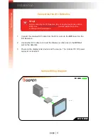
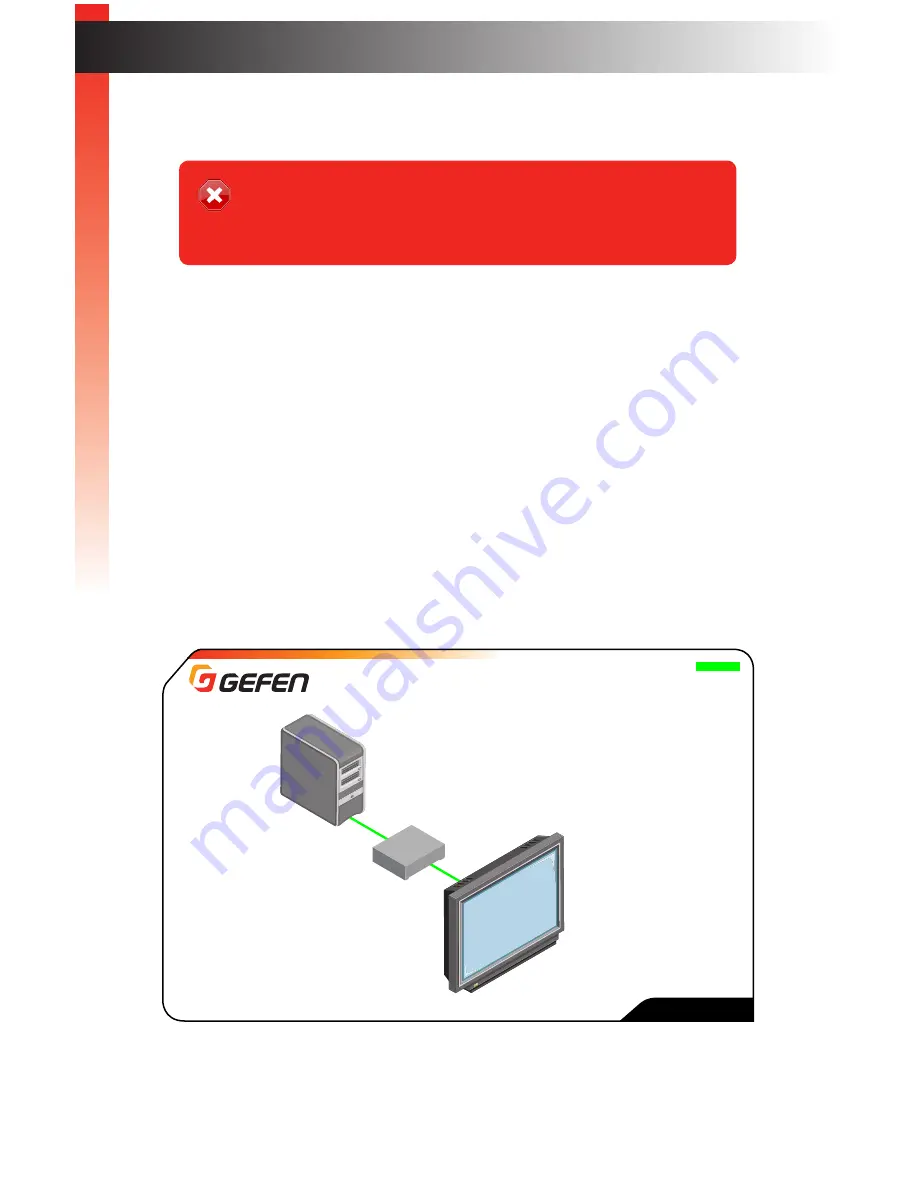
Sample Wiring Diagram

Installation

Stop!

Before connecting the DVI Detective, the unit must be programmed with an 

EDID.  See 

EDID Programming (page 8)

 for more information, before 

continuing with the installation.

Computer

Monitor

DVI Detective N

DVI CABLE

EXT-DVI-EDIDN

Ge

tting S

tar

ted

Summary of Contents for DVI Detective

Page 1: ...EXT DVI EDIDN User Manual Preferred DVI Detective ...

Page 2: ...rd from being walked on or pinched particularly at plugs convenience receptacles and the point where they exit from the apparatus 11 Only use attachments accessories specified by the manufacturer 12 To reduce the risk of electric shock and or damage to this product never handle or touch this unit or power cord if your hands are wet or damp Do not expose this product to rain or moisture 13 Unplug t...

Page 3: ...hout limitation any implied warranty or merchantability or fitness for any particular purpose all of which are expressly disclaimed 1 Proof of sale may be required in order to claim warranty 2 Customers outside the US are responsible for shipping charges to and from Gefen 3 Copper cables are limited to a 30 day warranty and cables must be in their original condition The information in this manual ...

Page 4: ...0 2K and 3840x2400 Dual Link EDID write protection switch No power is required after initial programming Packing List The following items are shipped with the DVI Detective If any of these items are not present in the box when you first open it immediately contact your dealer or Gefen 1 x DVI Detective 1 x 1 ft Dual Link DVI Cable M M 1 x 5V DC Power Supply 1 x Quick Start Guide Features and Packi...

Page 5: ...DVI Detective 1 Getting Started Introduction 2 Installation 4 Connecting the DVI Detective 4 Sample Wiring Diagram 4 ...

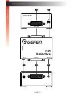
Page 6: ...page 2 Introduction DVI In Detective Power Prog EXT DVI EDIDN WR DVI Out E D DVI In DVI Detective Power Prog 5V DC EXT DVI EDIDN WR DVI Out E D 5 3 4 1 2 Getting Started Getting Started ...

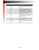
Page 7: ...programmed with an external EDID Set this switch to the D position to disable programming and prevent an accidental erasure of the current EDID 3 Prog Press this button to begin programming an EDID See EDID Programming page 8 for more information 4 DVI In Connect the DVI source to this port using the included DVI cable 5 Power This LED will glow bright red when the unit is powered Getting Started ...

Page 8: ...Out port on the detective 3 Power on the display sink device and the source The included 5V DC power supply is not required Sample Wiring Diagram Installation Stop Before connecting the DVI Detective the unit must be programmed with an EDID See EDID Programming page 8 for more information before continuing with the installation Computer Monitor DVI Detective N DVI CABLE EXT DVI EDIDN Getting Start...

Page 9: ...page 7 DVI Detective 2 Basic Operation EDID Programming 8 LED Status 9 ...

Page 10: ...D to be recorded 2 Connect a DVI cable from the sink device to the DVI Out port on the DVI Detective 3 Move the WR switch to the E position in order to allow the EDID to be written to the DVI Detective 4 Connect the included 5V DC power supply to the DVI Detective The Power LED on the other side of the unit will glow solid red 5 Press and release the Prog button The Power LED will flash as the EDI...

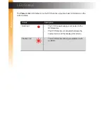
Page 11: ...ovides basic information on the current status Status Description Solid red The 5V DC power supply is connected to the DVI Detective The DVI Detective is connected between the source device and the display sink device Flashes red The DVI Detective is being programmed with an EDID ...

Page 12: ...DVI Detective 3 Appendix Specifications 12 ...

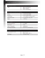
Page 13: ...in female Programming 1 x Push button momentary switch Write protect switch 1 x two position slide switch Power 1 x LED red Operational Maximum Pixel Clock 2 x 165 MHz Power Input 5V DC Power Consumption 5 Watts max Operating Temperature 41 to 113 F 5 to 45 C Physical Dimensions W x H x D 2 6 x 1 8 x 1 2 66mm x 46mm x 30mm Unit Weight 0 18 lbs 0 08 kg Specifications Appendix ...

Page 14: ...Stretch it Switch it Split it Gefen s got it Preferred ...

Reviews: