background image

BACK PANEL DESCRIPTIONS

1  5V DC 

Connect the included 5V DC locking power supply to this receptacle.

2  In 1 - In 8 

Each of these ports will accept a standard DisplayPort source device.

3  Ext IR 

Connect an IR extender cable to this port.

4  USB Out (1 - 2) 

Connect USB devices (e.g. mouse devices, keyboards, etc.) to these ports.

5  Ethernet


Use an Ethernet cable to connect the Switcher to a network in order to 

communicate via Telnet.

6  RS-232 Serial Port 

This port is used for serial communication using an RS-232 control device.  For 

details, refer to page 14.

7  USB In (1 - 8)


Connect USB source devices to these ports.

8  DP Out 

This port will accept a single standard DisplayPort output device.  The currently 

selected DisplayPort input source will be output via this port.

9  Audio Out  

Connect an audio output device to this connectors using a 3.5 mm mini-stereo 

cable.  The audio output will be for the currently selected input source.

10  Audio In (1 - 8) 

Connect up to eight (8) audio source devices to these ports using the included 

3.5 mm mini-stereo cables. 

Summary of Contents for EXT-DPKVM-841

Page 1: ... 8x1 DPKVM Switcher EXT DPKVM 841 User Manual ...

Page 2: ...rms with or without modification are permitted provided that the following conditions are met 1 Redistributions of source code must retain the above copyright notice this list of conditions and the following disclaimer 2 Redistributions in binary form must reproduce the above copyright notice this list of conditions and the following disclaimer in the documentation and or other materials provided ...

Page 3: ...er in a studio or professional environment this versatile solution saves money supports both Mac and PC type computers and offers uncluttered and increased desktop space The 8x1 DPKVM Switcher outputs are One DisplayPort two USB 2 0 ports used for keyboard mouse and other USB 2 0 peripherals and an analog L R audio This Switcher can be controlled using front panel discrete switching IP control the...

Page 4: ... The Switcher will use the EDID from the currently active input Dual Link resolutions up to 2560 x 1600 are supported HDCP content is not supported This Switcher does not support DHCP The default IR channel for both the Switcher and the IR Remote Control Unit is channel 0 See page 10 for more information OPERATION NOTES ...

Page 5: ... or Ethernet RS 232 control IP control IR remote control Supports USB 2 0 with backward compatibility for USB 1 1 Standby Feature Green Mode Control via Telnet Jack for external IR Receiver EXT RMT EXTIR Save space on your desktop Rack mountable Package Includes 1 8x1 DPKVM Switcher 8 6 ft DisplayPort cables 8 6 ft USB 2 0 cables A B 8 6 ft 3 5 mm mini stereo audio cables 1 IR Remote Control Unit ...

Page 6: ...FRONT PANEL LAYOUT Front Panel 4 2 1 3 ...

Page 7: ...t blue according to the input selection see Input Buttons below 2 IR Receives IR signals from the included IR Remote Control Unit 3 Input Buttons 1 8 Pressing each of these buttons selects the desired input source 1 8 4 Power This LED indicator will glow bright red when the unit is powered ...

Page 8: ...BACK PANEL LAYOUT Back Panel 5 2 8 9 6 7 3 4 1 10 ...

Page 9: ...lnet 6 RS 232 Serial Port This port is used for serial communication using an RS 232 control device For details refer to page 14 7 USB In 1 8 Connect USB source devices to these ports 8 DP Out This port will accept a single standard DisplayPort output device The currently selected DisplayPort input source will be output via this port 9 Audio Out Connect an audio output device to this connectors us...

Page 10: ...pressed 2 Source Selection Buttons 1 8 These buttons are used to select which source is routed to a monitor Layout and Description 1 NOTE An Activity Indictor that flashes quickly while holding down any one of the eight buttons indicates a low battery Replace the IR Remote Control battery as soon as possible ...

Page 11: ...pen battery slot The positive side of the battery should be facing up 3 Replace the battery cover The Remote Control unit ships with two batteries One battery is required for operation and the other battery is a spare WARNING Risk of explosion if battery is replaced by an incorrect type Dispose of used batteries according to the instructions Battery Slot ...

Page 12: ...channel on the 8x1 DPKVM Switcher IR Channel 0 default 1 2 ON Setting the IR Channel In the event that IR commands from other remote controls interfere with the supplied IR Remote Control unit changing the IR Remote Control s IR channel will fix the problem The IR Remote Control unit has a bank of DIP switches used for setting the IR channel The DIP switch bank is located underneath the battery co...

Page 13: ...rk See page 24 for more information on using the Telnet feature c OPTIONAL To extend the range of the IR control connect an IR Extender Gefen part no EXT RMT EXTIR to the back of the Switcher 3 Connect the included 5V locking power supply to the power receptacle on the 8x1 DPKVM Switcher 4 Connect the opposite end of the power supply to an open wall socket power source Wiring Diagram for the 8x1 D...

Page 14: ... panel buttons Example Switch to input 5 using the front panel buttons 1 Press button 5 on the front panel of the 8x1 DPKVM Switcher 2 The LED indicator for input 5 will glow bright blue on the front panel Switching sources using the IR Remote Control Example Switch to Input 1 using the IR Remote Control 1 Press button 1 on the IR Remote Control Unit The Activity Indicator on the IR Remote Control...

Page 15: ...formation on RS 232 commands RS 232 commands are case sensitive 2 The LED indicator for Input 4 will glow bright blue on the front panel Switching sources using Telnet Configure the Switch for use with Telnet See page 24 for details Example Switch to Input 2 using the Telnet protocol 1 Use the command r 2 to route the Switcher to Input 2 2 The LED indicator for Input 2 will glow bright blue 2 2 r ...

Page 16: ... 5 Ground are used on the RS 232 serial interface Serial Port Settings Bits per second 19200 Data bits 8 Parity None Stop bits 1 Flow Control None NOTE Only pins 2 Receive 3 Transmit and 5 Ground are used for communication A null modem adapter should not be used with this product IMPORTANT When sending RS 232 commands a carriage return and a line feed character must be included at the end of each ...

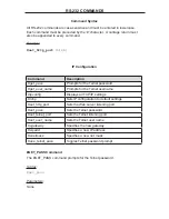
Page 17: ...ts for the Telnet username ipconfig Displays all TCP IP settings rstip Sets IP configuration to default settings set_http_port Sets the Web server listening port set_pass Sets the Telnet password set_telnet_port Sets the Telnet listening port set_user_name Sets the Telnet user name sgateway Specifies the new gateway sipadd Specifies a new IP address snetmask Specifies a new net mask use_telnet_pas...

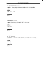
Page 18: ... for the Telnet username Syntax get_user_name Parameters None IPCONFIG Command The IPCONFIG command displays all TCP IP settings Syntax ipconfig Parameters None RSTIP Command The RSTIP command resets the IP configuration to the default settings Syntax rstip Parameters None ...

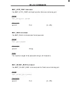
Page 19: ... param1 Port 0 255 SET_PASS Command The SET_PASS command sets Telnet password Syntax set_pass param1 Parameters param1 String Notes The maximum length of the password string is 20 characters SET_TELNET_PORT Command The SET_TELNET_PORT command sets the Telnet server listening port Syntax set_telnet_port param1 Parameters param1 Port 0 255 ...

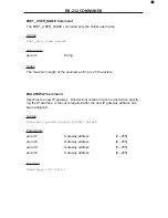
Page 20: ...0 characters SGATEWAY Command Specifies the new IP gateway Dot decimal notation must be used when specify ing the IP address A reboot is required after the new IP gateway address has been assigned Syntax sgateway param1 param2 param3 param4 Parameters param1 Gateway address 0 255 param2 Gateway address 0 255 param3 Gateway address 0 255 param4 Gateway address 0 255 Example sgateway 192 168 1 1 ...

Page 21: ... 255 param2 IP address 0 255 param3 IP address 0 255 param4 IP address 0 255 Example sipadd 192 168 2 240 SNETMASK Command The SNETMASK command specifies a new net mask Dot decimal notation must be used when specifying the IP address A reboot is required after the new IP address is set Syntax snetmask param1 param2 param3 param4 Parameters param1 IP address 0 255 param2 IP address 0 255 param3 IP ...

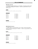
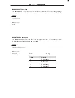
Page 22: ...vebolo Activates the bootloader fadefault Resets the Switcher to the default routing state irrmtadd Sets the IR address for the Switcher lockpower Toggles the lock power state stbymode Toggles Standby power OFF Mode ACTIVEBOLO Command The ACTIVEBOLO function activates the bootloader This command is required in order to begin the firmware update procedure See page 26 for details Syntax activebolo P...

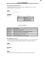
Page 23: ...ting settings Syntax fadefault Parameters None IRRMTADD Command The IRRMTADD sets the IR channel The IR channel for the Switcher and the IR Remote Control Unit must be the same Syntax irrmtadd param1 Parameters param1 State 0 3 Value Meaning 0 IR channel 0 1 IR channel 1 2 IR channel 2 3 IR channel 3 ...

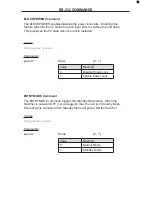
Page 24: ...restarted Syntax lockpower param1 Parameters param1 State 0 1 Value Meaning 0 Disable Power Lock 1 Enable Power Lock STBYMODE Command The STBYMODE command toggles the Standby Mode state When the Switcher is powered OFF not unplugged then the unit is in Standby Mode Executing this command from Standby Mode will power ON the Switcher Syntax stbymode param1 Parameters param1 Mode 0 1 Value Meaning 0 ...

Page 25: ...t require the character A carriage return must be added to the end of the command Command Description R Routing command R Command The R command switches to the specified input Syntax r param1 Parameters param1 DisplayPort Input 1 8 RS 232 COMMANDS ...

Page 26: ... g HyperTerminal PuTTY Indigo etc to connect to the Switcher See page 14 for information on RS 232 configuration 3 Apply power to the Switcher Information similar to the following will be displayed in the terminal window GEFEN DISPLAY PORT 841 FW version 1 3 4 Use the ipconfig command to display the current IP settings The factory default settings are displayed below ipconfig TCP IP settings MAC a...

Page 27: ...reen similar to the following Welcome to DP841 Telnet Server You are user number 1 of 3 allowed You will be disconnected after 10 minutes of inactivity Login Admin Password Admin Type Cmd By default the user name and password options are enabled by use of the use_telnet_pass command see page 20 Once this command is enabled the Switcher will prompt for both the user name and password The password c...

Page 28: ... key 3 Repeat Step 2 The following will be displayed on the screen Main Menu Download new program 1 Cancel 2 4 Press 1 on the computer keyboard to begin downloading program to the htemporary memory 5 The following message will be displayed Waiting for the file to be sent press a to abort 6 In Hyperterminal click Transfer Send File 7 Click Browse and select the bin file to be uploaded e g 1x4splitt...

Page 29: ...unit into a 1U rack mount space 1 Locate the side screws on the unit 2 Remove the front 2 screws that are located closest to the front of the unit 3 Using the removed screws screw the rack mounting bracket into the unit 4 Repeat the procedure on the opposite side of the unit Rear of unit Front of unit ...

Page 30: ...Type B female USB Device Connectors 2 USB 2 0 Type A female Audio Input Connectors 8 3 5 mm mini stereo jack Audio Output Connector 1 3 5 mm mini stereo jack IR Extender Connector 1 3 5 mm mini stereo jack RS 232 Control Connector 1 DB 9 female Power Supply 5V DC Locking Dimensions W x H x D 17 1 x 1 75 x 4 25 434mm x 44mm x 108mm Shipping Weight 12 lbs 5 4 kg ...

Page 31: ...including without limitation any implied warranty or merchantability or fitness for any particular purpose all of which are expressly disclaimed 1 Proof of sale may be required in order to claim warranty 2 Customers outside the US are responsible for shipping charges to and from Gefen 3 Copper cables are limited to a 30 day warranty and cables must be in their original condition The information in...

Reviews: