background image

page | 7

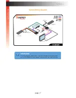
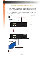
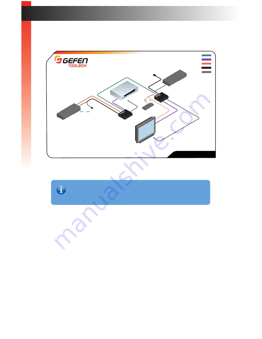
Sample Wiring Diagram

Installation

CAT-5 CABLE 

HDMI CABLE

RS-232 CABLE

IR IN

IR Emitter

RS-232 Controlled 
Device

IR Emitter

Ultra HD Display

Ultra HD Source

Sender Unit

Receiver Unit

OR

IR OUT

GTB-UHD-HBT

IR Extender

(EXT-RMT-EXTIRN)

OR

OR

Automation

Control Device

Automation

Control Device

IR Extender

(EXT-RMT-EXTIRN)

Ge

tting S

tar

ted

Information

The wiring diagram, shown above, requires an additional IR emitter (Gefen 

part no. EXT-IREMIT) and IR extender (Gefen part no. EXT-RMT-EXTIRN).

Summary of Contents for GTB-UHD-HBT

Page 1: ...GTB UHD HBT User Manual Release A0 6 HDBaseT Extender w RS 232 2 way IR and POH 60Hz 4 2 0...

Page 2: ...d from being walked on or pinched particularly at plugs convenience receptacles and the point where they exit from the apparatus 11 Only use attachments accessories specified by the manufacturer 12 To...

Page 3: ...purpose all of which are expressly disclaimed Warranty period begins on the date of purchase by the original end purchaser as indicated on the proof of purchase document This Limited Warranty extends...

Page 4: ...0 AM to 5 00 PM Monday Friday Pacific Time Email support gefen com Web http www gefen com Mailing Address Gefen Core Brands LLC c o Customer Service 1800 S McDowell Blvd Petaluma CA 94954 USA Product...

Page 5: ...t maximum distance please make sure that the DIP Switch 3 on the bottom of the Sender unit is in OFF position To enable the Extended Range up to 150m 495ft mode flip the DIP switch to ON Please see DI...

Page 6: ...cable up to 495 feet 150 meters 8 bit color HDMI Features Supported HDMI 2 0 HDCP 2 2 and 1 4 12 bit Deep Color LPCM 7 1 audio Dolby TrueHD and DTS HD Master Audio pass through 3DTV pass through CEC p...

Page 7: ...ender unit GTB UHD HBT S 1 x 4K Ultra HD HDBaseT Extender w RS 232 2 way IR and POL Receiver unit GTB UHD HBT R 1 x 6 ft locking HDMI cable M M CAB HD LCK 06MM 1 x IR extender EXT RMT EXTIRN 1 x IR em...

Page 8: ...Controlling the Display from the Source Location 12 Controlling the Source Display from Different Locations 13 DIP Switch Configuration 14 EDID Management 15 HPD Mode 16 HDBT HDBaseT Mode 17 RS 232 Mo...

Page 9: ...This page left intentionally blank...

Page 10: ...This page left intentionally blank...

Page 11: ...1 Getting Started HDBaseT Extender w RS 232 2 way IR and POH 60Hz 4 2 0...

Page 12: ...HD HDBaseT Extender S RS 232 Power Link 24V DC HDMI In Link IR In Ext IR Out GTB UHD HBT S w RS 232 2 way IR and POL 4K Ultra HD HDBaseT Extender S RS 232 Power Link 24V DC HDMI In Link IR In Ext IR...

Page 13: ...1 pc included from this port to the IR sensor of the device to be controlled See Bidirectional IR Control page 11 for more information on using IR 4 24V DC This power receptacle can be used to connec...

Page 14: ...a HD HDBaseT Extender R RS 232 Power Link 24V DC HDMI Out Link IR In Ext IR Out GTB UHD HBT R w RS 232 2 way IR and POL 4K Ultra HD HDBaseT Extender R RS 232 Power Link 24V DC HDMI Out Link IR In Ext...

Page 15: ...IT 1 pc included from this port to the IR sensor of the device to be controlled See Bidirectional IR Control page 11 for more information on using IR 4 24V DC This power receptacle can be used to conn...

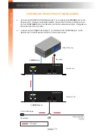
Page 16: ...ect the included 3 pin Phoenix to DB 9 female cable between the RS 232 controller and the Sender unit 6 Connect the included 3 pin Phoenix to DB 9 male cable between the RS 232 device and the Receiver...

Page 17: ...play Ultra HD Source Sender Unit Receiver Unit OR IR OUT GTB UHD HBT IR Extender EXT RMT EXTIRN OR OR Automation Control Device Automation Control Device IR Extender EXT RMT EXTIRN Getting Started Inf...

Page 18: ...This page left intentionally blank...

Page 19: ...page 9 2 Basic Operation HDBaseT Extender w RS 232 2 way IR and POH 60Hz 4 2 0...

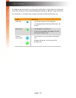
Page 20: ...ormation in the table below applies to both the Sender and Receiver unit Status Description Solid blue The Sender Receiver unit is powered Link integrity between Sender and Receiver unit is good Solid...

Page 21: ...ransmited over the Link cable 2 Connect an EXT IREMIT IR Emitter 1 pc included from the IR Out port on the Sender unit to the IR sensor window on the source device page 11 Bidirectional IR Control Bas...

Page 22: ...nnect an EXT IREMIT IR Emitter 1 pc included from the IR Out port on the Receiver unit to the IR sensor on the display page 12 Bidirectional IR Control Basic Operation IR signals Link IR In Ext IR Out...

Page 23: ...mited over the Link cable page 13 IR signals Bidirectional IR Control Sender unit Receiver unit Link IR In Ext IR Out GTB UHD HBT R Link IR In Ext IR Out GTB UHD HBT S w RS 232 2 way IR and POL 4K Ult...

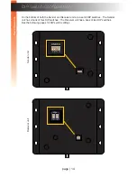
Page 24: ...DIP switches The Receiver unit has a bank of two DIP switches See the following pages for DIP switch settings Basic Operation Basic Operation ON RSN 1 2 3 4 Power Link 24V DC HDMI In Link IR In Ext I...

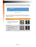
Page 25: ...d POL provides EDID management The Sender unit can use the EDID from the sink device downstream EDID or modify the EDID locally Description Sender unit Receiver unit External EDID mode default Allows...

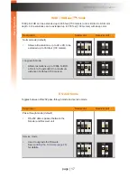
Page 26: ...Receiver unit HPD High Both DIP switch 1 and 2 must be in the down OFF position when setting HPD high HPD is always high even when the display is hot plugged disconnected from then reconnected to the...

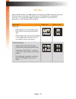
Page 27: ...g reach mode Allows resolutions up to 1080p Full HD at 8 bit to be extended to a maximum distance of 495 feet 150 meters RS 232 Mode Toggles between RS 232 pass through mode and service mode Descripti...

Page 28: ...This page left intentionally blank...

Page 29: ...3 Advanced Operation HDBaseT Extender w RS 232 2 way IR and POH 60Hz 4 2 0...

Page 30: ...28 for details 1 Connect the included 3 pin Phoenix to DB 9 M F adapter cable from the Sender unit to the automation device 2 Connect the included 3 pin Phoenix to DB 9 M M adapter cable from the Rece...

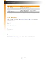
Page 31: ...ilable RS 232 commands power_always Enables disables power always mode fw_upgrade Used to upgrade the firmware See Updating the Firmware page 28 for information on using this command Syntax fw_upgrade...

Page 32: ...isplay is detected Set param1 0 to force the computer to ignore detection of an HDCP compliant display Syntax hdcp param1 Parameters param1 Integer 0 1 Value Description 0 Disable HDCP 1 Enable HDCP E...

Page 33: ...p on a specific command can be displayed when using param1 Syntax help param1 Parameters param1 Command name optional Example help Available cmds help fw_upgrade hdcp power_always help hdcp Cmd hdcp C...

Page 34: ...must be rebooted after changing the power mode Syntax power_always param1 Parameters param1 Integer 0 1 Value Description 0 Power save 1 Power always Example power_always 1 Set Power always mode To c...

Page 35: ...This page left intentionally blank...

Page 36: ...This page left intentionally blank...

Page 37: ...4 Appendix HDBaseT Extender w RS 232 2 way IR and POH 60Hz 4 2 0...

Page 38: ...unit The update procedure can take place at the Sender or Receiver location 1 Download the latest firmware here http www gefen com support download jsp 2 Extract the contents of the zip file to the d...

Page 39: ...nder or Receiver unit 9 Type the following in the terminal application fw_upgrade 10 Press the ENTER key 11 When prompted press 1 on the computer keyboard 12 Click Transfer Send File 13 Select the fir...

Page 40: ...ver unit from the system Make sure the power is disconnected from both the Sender and Receiver unit 4 Set the following DIP switches on the Sender and Receiver units Sender unit Set DIP switch 4 on th...

Page 41: ...ng in the terminal application fw_upgrade 10 Press the ENTER key 11 When prompted press 1 on the computer keyboard 12 Click Transfer Send File 13 Select the firmware file ELR_BIDIR_ version bin 14 Sel...

Page 42: ...nection and disconnection of the cables please leave sufficient clearance between the two edges of the unit that house the connectors and any walls or vertical surfaces For installation on a drywall s...

Page 43: ...Data positive differential signal 4 Blue Unused 5 Blue White Unused 6 Green RD Receive Data negative differential signal 7 Brown White Unused 8 Brown White Unused Shielded STP CAT 5 or CAT 6 is recomm...

Page 44: ...iver 1 x 3 5mm female RS 232 Sender Receiver 1 x 3 pin Phoenix type female Power Sender Receiver 1 x 4 pin locking female Power Link Sender Receiver 1 x LED bi color blue green Operational Maximum Pix...

Page 45: ...6 I Installation 6 L LED Status 10 Long reach mode 17 M Mounting Instructions 32 N Network Cable Diagram 33 O Operating Notes v P Packing List vii R Receiver Unit 4 RS 232 commands 21 mode 17 RS 232 S...

Page 46: ...Chatsworth CA 91311 1 800 545 6900 818 772 9100 fax 818 772 9120 www gefen com support gefen com Stretch it Switch it Split it Gefen s got it Preferred 1800 S McDowell Blvd Petaluma CA 94954 707 283...

Reviews: