User manual ADV200-…-SI with External Safety Modules
Page 8 of 13
4 Wiring and Installation
Running the safety functions requires one or both of the following configurations:
•
STO (
EXP-SFTy-ADV
) Safety Interface (*) installed on all drives with the "SI" suffix (e.g., ADV200-…-SI)
•
Optional Encoder Card installed on the ADV200-…-SI (EXP-DE/EXP-SE) drives.
The requirement for one or both would depend on which basic functions are to be used. For choosing the most
suitable configuration, see the respective specifications under table 1.
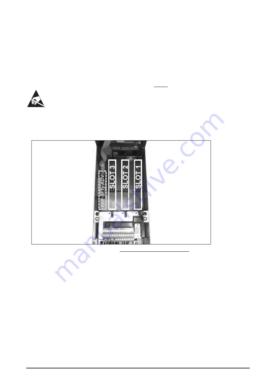
The cards are to be installed in the proper slots as shown in Figure 1:
•
Encoder cards must be installed in either slot 1, 2 or 3. For details, see the ADV200-QS User Manual.
•
(*) STO Safety Interface is factory-installed as card in its special slot (EXP-SFTy-ADV)
or integrated in the INT-P-ADV
power card (sizes ≥ 71600 from “L” HW version). For more details, see the ADV200 QS manual (cod 1S9H49) and
the STO safety function manual (code 1S5F94, Safety manual -EN).
Figure 1.
ADV200 slot diagram for optional cards
4.1 Encoder wiring
Motor speed data is required for many safety functions to run, namely the following:
•
SLS (Safe Limited Speed)
•
SDI (Safe Direction)
•
SS1 (Safe Stop 1)
To ensure the safety of speed data, more than one channel/reading-sensor must be used so as to guarantee
the integrity of data read by the sensor.
The possible position sensors combinations are as follows:
•
Encoder TTL/ proximity sensors
•
Encoder TTL/ 2
nd
encoder TTL/sincos
In the first case, if not in conflict with other problems, a single-channel Reer speed module (MV1x) should be
used. In the second case, when a dual encoder is installed, a double-channel ReeR speed module (MV2x)
should be used.


