background image

24

917334/BP0310

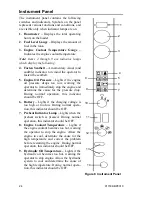
Instrument Panel

The instrument panel contains the following
switches and indicators. Symbols on the panel
represent various functions and conditions, and
are visible only when indicator lamps are on.

1. Hourmeter


 Displays the total operating

hours on the loader.

2. Fuel Level Gauge –

 Displays the amount of

fuel in the tank.

3. Engine Coolant Temperature Gauge –

Indicates the engine coolant temperature.

Note:  Items 4 through 9 are indicator lamps
which display the following:

4. Fasten Seatbelt –

 A momentary visual (and

audible) indicator to remind the operator to
fasten the seatbelt.

5. Engine Oil Pressure –

 Lights if the engine

oil pressure drops too low, warning the
operator to immediately stop the engine and
determine the cause for the pressure drop.
During normal operation, this indicator
should be OFF.

6. Battery –

 Lights if the charging voltage is

too high or too low. During normal opera-
tion, this indicator should be OFF. 

7. Preheat Indicator Lamp –

 Lights when the

preheat switch is pressed. During normal
operation, this indicator should be OFF.

8. Engine Coolant Temperature –

 Lights if

the engine coolant becomes too hot, warning
the operator to stop the engine. Allow the
engine to cool, determine the cause for the
high temperature and correct the problem
before restarting the engine. During normal
operation, this indicator should be OFF.

9. Hydraulic Oil Temperature –

 Lights if the

hydraulic oil becomes too hot, warning the
operator to stop engine. Allow the hydraulic
system to cool and determine the cause of
the high temperature. During normal opera-
tion, this indicator should be OFF.

1

2

3

4

5

6

7

8

Figure 8  Instrument Panel

9

10

11

12

13

14

Summary of Contents for SL3640E

Page 1: ...SL3640E SL3840E EU SL4240E SL4240E EU Skid Steer Loaders Operator s Manual Form No 917334 BP0310 English...

Page 2: ...o BE ALERT Your personal safety is involved Operators must have instructions before running the machine Untrained operators can cause injury or death Read Operator s Manual before using machine CORREC...

Page 3: ...cations 71 Table of Common Materials and Densities 76 Torque Specifications 79 Index 81 SL3640E SL3840E EU and SL4240E Operator s Manual TABLE OF CONTENTS All Tach and Hydraloc are trademarks of Gehl...

Page 4: ...below conforms to EC Directives 2004 108 EC EMC 97 23 EC Pressure Equipment 2006 42 EC Machinery and 2000 14 EC Noise Emission including all current amendments 7 In accordance with EN ISO Standards EN...

Page 5: ...the manual provided with the attachment to learn how to safely maintain and operate the equipment Be sure the machine is suitably equipped for the type of work to be performed Do not use this machine...

Page 6: ...Front Work Lights 5 Handholds 6 Lift Arm 7 Auxiliary Hydraulic Couplers 8 Tilt Cylinders 9 Attachment Bracket 1 2 3 4 5 6 8 9 7 1 Engine Cover 2 Tail Lights 3 Rear Work Lights 4 Rear Door 5 Roll Over...

Page 7: ...Lift Point N Neutral Safety Alert Chaincase Oil Seatbelt Lap Only Engine Air Filter Engine Oil Engine Oil Filter Engine Oil Pressure Fuel Filter Engine Coolant Temperature Hydraulic System Hydraulic...

Page 8: ...4 917334 BP0310 Notes...

Page 9: ...ed to hillside operation overloading insta bility of the load poor maintenance and using the equipment for a purpose for which it is not intended or designed Gehl ALWAYS considers the operator s safet...

Page 10: ...lling or cutting can weaken the structure and reduce the protection it provides A damaged ROPS FOPS cannot be repaired it must be replaced To ensure safe operation replace damaged or worn out parts wi...

Page 11: ...attachments because they could fall or cause an accident Always look to the rear before backing up the skid steer loader Operate the controls only from the operator s seat Always keep hands and feet...

Page 12: ...ing and often fatal lung disease A Hazard Review Pub No 2002 129 by the U S National Institute for Occupational Safety and Health NIOSH indicates a significant risk of chronic silicosis for workers ex...

Page 13: ...4 BP0310 9 Safety Decals inside the ROPS FOPS 137628 Located on manual box operator s right 137683 Located on ROPS left panel 137647 Located on operator s lower left side 137639 Located on ROPS left p...

Page 14: ...10 917334 BP0310 Safety Decals on the outside of the Skid Loader 137655 Front of loader 137720 Front of loader 184214 Under ROPS 137637 Lift arm support device loader left side...

Page 15: ...917334 BP0310 11 Safety Decals in the Engine Compartment 137657 Right of hydraulic filter 137658 On radiator...

Page 16: ...47 Part of left instrument panel Safety alert Always follow Mandatory Safety Shutdown Procedure in Operator s Manual 1 Lower equipment to ground 2 Reduce throttle stop engine 3 Apply parking brake rem...

Page 17: ...ll hazard No riders Never use work tool as work platform Crush hazard Before operating with attachment check engagement of hitch locking pin to the attachment A Incorrect attachment engagement C Lock...

Page 18: ...extinguisher nearby C Run over hazard Jump start per Operator s Manual procedure D Oil injection hazard Do not use hands to find hydraulic leaks Escaping oil under pressure can be invisible and penetr...

Page 19: ...el certification and operator protection system serial number 3 Product plate with Product Identification Number and e g model type designation 4 Seat plate according to ISO 7096 5 Component plate rea...

Page 20: ...16 917334 BP0310 Notes...

Page 21: ...dous areas In many places safety decals are also provided to warn of potential hazards and or to display special operating procedures Read and thoroughly understand all safety decals on the loader bef...

Page 22: ...efeat the safety interlock system by mechanically or electrically bypassing any switches relays or solenoid valves An interlock system is used on the loader for operator safety Together with solenoid...

Page 23: ...he ROPS FOPS Roll Over Falling Object Protective Structure is designed to provide protection for the operator from falling objects and in case the loader tips or rolls over provided the operator is se...

Page 24: ...ft arm using the lock pin The support device is a safety device that must be kept in proper operating condition at all times The following steps ensure correct usage The safest method of engaging the...

Page 25: ...nst the lift arm Allow the support device to drop down into contact with the lift cylin der 4 Return to the operator s compartment and start the engine 5 Raise the lift arm until the lift arm support...

Page 26: ...from the area 3 Before leaving the operator s compartment be sure that the lift arm is being held in the raised position by the solenoid valve 4 To store the support device raise it up until it conta...

Page 27: ...ve the control forward to increase the engine speed and rear ward to decrease the engine speed T Bar Controls Only A right foot operated accelerator pedal is provided to control the engine speed The p...

Page 28: ...ne the cause for the pressure drop During normal operation this indicator should be OFF 6 Battery Lights if the charging voltage is too high or too low During normal opera tion this indicator should b...

Page 29: ...e cannot be started unless the operator is sitting in the seat and the restraint bar is lowered 11 Parking Brake Switch Used to manually apply the parking brake The red indicator on the switch lights...

Page 30: ...neutral before starting the engine Operate the controls grad ually and smoothly Excessive speed and quick control movements without regard for conditions and circumstances are hazardous and could cau...

Page 31: ...hly Excessive speed and quick control movements without regard for conditions and circumstances are hazardous and could cause an accident Lift Tilt Controls Moving the lift arm and tilting the attachm...

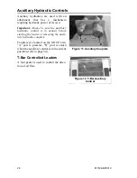
Page 32: ...lic control is in neutral before starting the loader or removing the auxil iary hydraulic couplers Couplers are located on the left lift arm A port is pressure B port is return when the auxiliary cont...

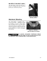
Page 33: ...r mounting a bucket or other attach ment Two latch levers secure the attach ment Rotate the levers until they are hori zontal to engage the latch pins Rotate the levers until they are vertical to dise...

Page 34: ...30 917334 BP0310 Notes...

Page 35: ...nt 2 Fasten the seatbelt and lower the restraint bar 3 Verify the following the lift tilt drive and auxiliary controls are in their neutral positions the brake is on 4 Push the throttle forward to hal...

Page 36: ...s off the engine or when the brake switch is applied Parking the Loader Park the loader on level ground away from traffic If this is not possible park the loader across the incline and block the tires...

Page 37: ...l negative jumper cable connection to the disabled loader s engine block or loader frame ground NOT to the disabled battery s negative post If connected to the engine keep the jumper clamp away from t...

Page 38: ...er forward and at the same time tilt the attachment bracket back to engage the flange on the back side of the attachment 6 Stop forward travel when the flange is engaged but continue to tilt the attac...

Page 39: ...d in contact with the loader frame 6 Tilt forward and slowly back the loader until the attachment is free from the loader Self Leveling optional The feature is designed to keep the attachment level wh...

Page 40: ...nd by driving for ward and gradually lowering the lift arm With the bucket filled tilt the bucket back and back the loader away from the material Rest the lift arm against the loader frame before proc...

Page 41: ...cket extends half way over the edge of the embank ment Tilt the bucket forward and raise the lift arm to dump the material After the material is dumped back away from the embankment while tilting the...

Page 42: ...ers in the operator s compartment while the loader is lifted Keep everyone a safe distance away from the loader while it is lifted Loader may only be lifted with an empty bucket or empty pallet forks...

Page 43: ...trac tion Move the loader on and off the vehicle ramp slowly and care fully Failure to follow these instructions could result in an overturn accident Observe all local regulations governing the loadi...

Page 44: ...40 917334 BP0310 Notes...

Page 45: ...Important More frequent service than the recommended intervals may be required under severe operating conditions You must decide if your operation requires more service Important Always dispose of was...

Page 46: ...aise the skid steer loader so all four tires are off the ground use the procedure below Do not rely on a jack or hoist to maintain the raised position without additional blocking and supports Serious...

Page 47: ...ments Control Handles The control handles do not require routine adjustment Refer to the Service Manual for the initial setup procedure Fuel Sender The fuel sender located in the fuel tank sends a sig...

Page 48: ...efer to the separate engine manual for more information regarding recommended engine lubricants quanti ties required and grades Refer to the following figure for grease fitting locations Wipe dirt fro...

Page 49: ...er If the air filter becomes restricted this indi cator will turn red to warn the operator that the element s require service Push the reset button located on the end of the indicator after fitting a...

Page 50: ...rt built up in the cover assembly Outer Element 1 Carefully pull the outer element out of the housing Never remove the inner element unless it is to be replaced 2 Clean out any dirt built up in the ho...

Page 51: ...ardware All bolts that secure the engine mounting brackets to the engine and the loader frame should be checked and re tightened as necessary Allow hot engine and hydraulic system compo nents to cool...

Page 52: ...mote oil drain hose Check the oil level Add oil if it is not at the top mark on the dipstick For a replacement element refer to the Replacement Parts topic page 43 Changing Fuel Filter The engine has...

Page 53: ...If red float is raised open valve on the bottom of the bowl to drain water 2 Close valve quickly after float reaches the bottom of the bowl Spark Arrestor Muffler Important The loader is factory equi...

Page 54: ...ere the element seal contacts the housing Put clean oil on the rubber gasket of the new filter element 3 Install and tighten the filter element 3 4 of a turn past the point where the gasket contacts t...

Page 55: ...ce lower the lift arm and stop the engine Allow the engine to cool 2 Open the rear door Lift the engine cover 3 Clean the radiator and oil cooler by blowing through the fins with high pres sure water...

Page 56: ...rication topic page 44 for information on oil type and quantity Checking and Adding Oil 1 Park the loader on a level surface Stop the engine 2 Remove the check plug from each chaincase housing If the...

Page 57: ...lating or servicing tires can be dangerous When possible trained personnel should service and mount tires To avoid possible death or serious injury follow the safety precautions below 1 Be sure the ri...

Page 58: ...e tires with the same size as the original equipment Electrical System Circuit Breakers The circuit breakers for the loader are located on the right instrument panel There is also a 35 amp main circui...

Page 59: ...in use or being charged Keep flames or sparks away from the battery area ALWAYS charge the battery in a well ventilated area Never lay a metal object on top of a battery because a short circuit can re...

Page 60: ...56 917334 BP0310 Notes...

Page 61: ...and locate trouble before resetting breaker Battery terminals or cables are loose or corroded Clean battery terminals and cables and retighten them Seatbelt buzzer not sounding when key turned to ON...

Page 62: ...cted Check wiring for poor connections broken leads repair wiring or connection Starter or pinion faulty Remove starter repair replace as needed Work lights not functioning properly Single light doesn...

Page 63: ...enoid not energizing Check electrical connections and voltage to shut off solenoid Engine oil not warm enough Install a pan heater Ambient temperature is too low Install a pan heater Fuel pump not wor...

Page 64: ...od linkage disconnected Check linkage connection at control levers and neutral centering mechanisms Reconnect linkage Low or no charge pressure Contact your dealer Hydrostatic pump s relief valves are...

Page 65: ...ed continuously Improve efficiency of operation Drive motor s or hydrostatic pump s have internal damage or leakage Contact your dealer Oil cooler fins plugged with debris Clean oil cooler fins Loader...

Page 66: ...dealer Relief valves on rear hydrostatic pump malfunctioning Contact your dealer Control rod linkage to rear hydrostatic pump disconnected Attach control rod linkage Right side doesn t drive in forwar...

Page 67: ...er Restraint bar switch malfunctioning Check electrical connections to restraint bar switch and repair connections as needed If switch is still not functioning properly contact your dealer Hydraulic c...

Page 68: ...o down pressure on the bucket Control valve in float position Take control out of float position Tilt cylinders are malfunctioning Contact your dealer Relief valve in control valve not functioning pro...

Page 69: ...ler Oil leaking past lift spool in control valve Contact your dealer Self leveling valve malfunctioning Contact your dealer Leaking hydraulic hoses tubes or fittings between control valve and cylinder...

Page 70: ...66 917334 BP0310 Notes...

Page 71: ...orm the maintenance at 1000 hours Maintenance Interval Chart Service Procedure Maximum Interval 10 Hours or Daily 250 Hours 500 Hours or Yearly Check Engine Air Cleaner Restriction Indicator page 45 z...

Page 72: ...68 917334 BP0310 Maintenance Log Date Hours Service Procedure...

Page 73: ...917334 BP0310 69 Maintenance Log Date Hours Service Procedure...

Page 74: ...70 917334 BP0310 Notes...

Page 75: ...8 BKMS Displacement 100 in3 1 64 L 133 in3 2 19 L Power net 35 hp 26 kW 2600 rpm 46 hp 34 kW 2600 rpm Peak Torque 80 ft lbs 108 N m 1200 rpm 103 ft lbs 140 N m 1200 rpm Hydraulic System theoretical Ma...

Page 76: ...ual Front and Rear Work Lights Removable Belly Plate and Access Cover Dual Element Air Cleaner with Visual Indicator Vandalism Lock Provisions Top and Rear Windows Spark Arrestor Muffler Headliner and...

Page 77: ...42o F Dump Height 84 5 2146 G Dump Reach Bucket Full Height 22 8 579 J Rollback at Ground 29o M Rollback Angle at Full Height 99o O Seat to Ground Height 32 6 828 P Wheel Base Nominal 34 5 876 Q Over...

Page 78: ...Dump Height 84 5 2197 G Dump Reach Bucket Full Height 20 8 528 J Rollback at Ground 29o M Rollback Angle at Full Height 99o O Seat to Ground Height 33 6 853 P Wheel Base Nominal 36 7 932 Q Overall Wid...

Page 79: ...g 1325 lbs 601 kg 61 5 in 13 0 ft3 1562 mm 0 37 m3 383 lbs 174 kg 975 lbs 422 kg 1214 lbs 551 kg Utility Buckets 55 5 in 13 5 ft3 1410 mm 0 38 m3 313 lbs 142 kg 1061 lbs 481 kg 1325 lbs 601 kg 61 5 in...

Page 80: ...al 53 63 848 1008 Concrete 115 1840 Cinders 50 800 Coal anthracite 94 1504 Coke 30 480 Earth dry loam 70 90 1121 1442 Earth wet loam 80 100 1281 1602 Granite 93 111 1488 1776 Gravel dry 100 1602 Grave...

Page 81: ...l loader using Dirt Construction Bucket the bucket capacity is 10 5 ft3 and the loader rating is 1050 lbs Multiply the density of snow 50 lbs ft3 by the capacity of the bucket 10 5 ft3 to achieve the...

Page 82: ...78 917334 BP0310 Notes...

Page 83: ...50 56 9 9 9 10 17 19 75 86 13 14 12 14 25 25 9 10 18 20 3 8 16 3 8 24 7 16 14 7 16 20 20 23 32 36 15 17 24 27 30 35 50 55 23 25 35 40 45 50 70 80 35 35 55 60 1 2 13 1 2 20 9 16 12 9 16 18 50 55 70 80...

Page 84: ...TINUE TO APPLY SOME STATES DO NOT PERMIT THE EXCLUSION OF LIMITATION OF THESE WARRANTIES AND YOU MAY HAVE GREATER RIGHTS UNDER YOUR STATE LAW GEHL WARRANTY DOES NOT INCLUDE 1 Transportation to selling...

Page 85: ...tings 75 Chaincases 52 Checking and Adding Oil 52 Draining Oil 52 Circuit Breakers 54 Cold Starting Procedure 31 Control Indicator Symbols 3 CONTROLS and SAFETY EQUIPMENT 17 Cooling System 51 Check Co...

Page 86: ...fety Reminders 6 Self Leveling 35 SERVICE 41 Spark Arrestor Muffler 49 SPECIFICATIONS 71 Accessories 72 Standard Features 72 Starting the Engine 31 Before Starting the Engine 31 Stopping the Loader 32...

Page 87: ...raised Load unload and turn on flat level surface WRONG Never carry riders Keep bystanders away from work area WRONG Never modify equipment Use only attachments approved for the loader WRONG Never lea...

Page 88: ...u have any questions on proper operation adjustment or maintenance of this machine contact your dealer or the Gehl Company Service Department before starting or continuing operation Gehl Company One G...

Reviews: