


GEKCO DIGITAL CLOCK P/N CLK056 ASSEMBLY & OPERATION MANUAL
12
REV 1.0
GEKCO INC.
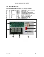
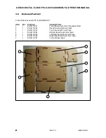
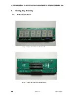
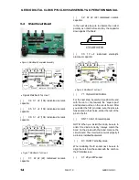
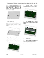
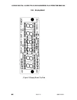
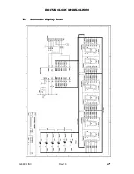
Position the Display Circuit Board with the component side facing up as shown below
C1
R1
C2
LED5
LED6
LED4
LED3
Figure 4: Display Board Top Side Assembly Pictorial
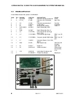
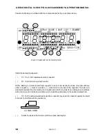
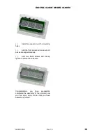
Install the decoupling capacitor.
( )
C1: 0.1 uF (104) radial-lead ceramic capacitor
( )
R1: 10 k
(brn-blk-org-silver) resistor
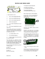
NOTE: Before you install an electrolytic capacitor, look at it and identify the leads. One lead will have
either a negative (
) mark or a positive (
) mark near it on the side of the capacitor. The aluminum
electrolytic capacitor has the marking for a negative lead which may look like an oblong bar, sometimes
with a circle around it, inside an arrow. Be sure to install the positive lead in the positive-marked hole.
( )
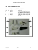
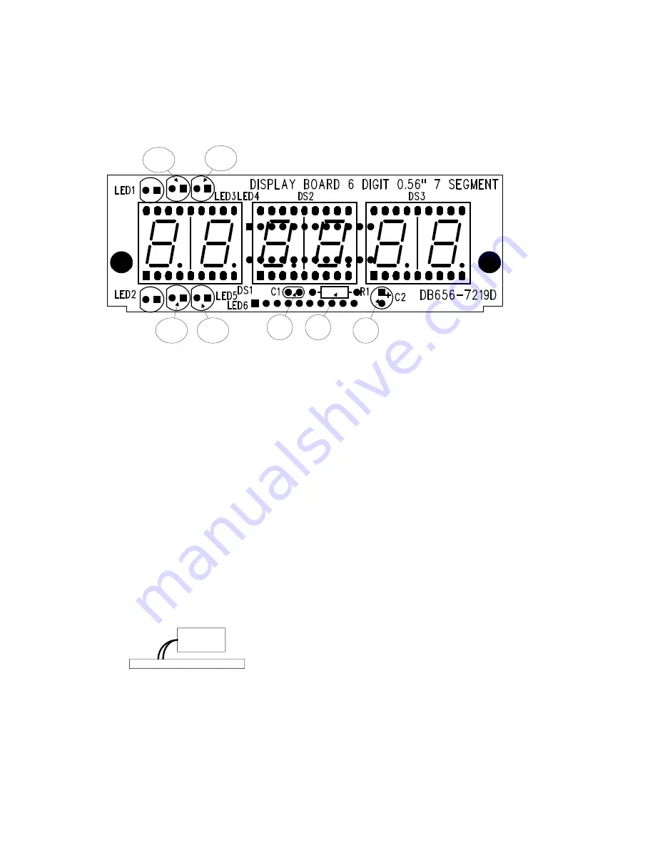
C2: 10 uF radial-lead electrolytic aluminum capacitor (lay down the capacitor against the board
so it does not interfere with the enclosure)
C2 SIDE VIEW
( )
Solder the leads to the foil and cut off the excess lead lengths.