


GEKCO DIGITAL CLOCK P/N CLK056 ASSEMBLY & OPERATION MANUAL
14
REV 1.0
GEKCO INC.
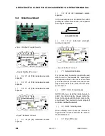
5.2.
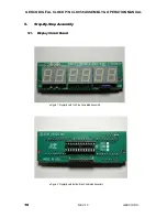
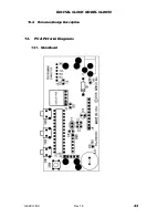
Main Circuit Board
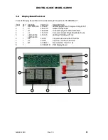
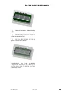
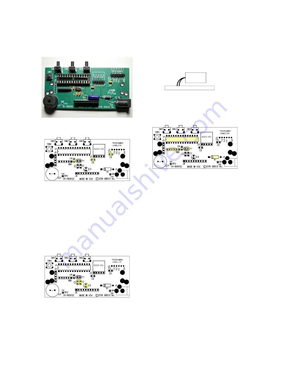
Figure 5: Main Board Completed Assembly
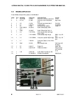
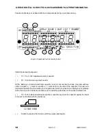
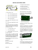
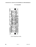
Figure 6 Main Board Top View 1
( )
C4: 0.1 uF (104) radial-lead ceramic
capacitor
( )
C5: 0.1 uF (104) radial-lead ceramic
capacitor
( )
C6: 0.1 uF (104) radial-lead ceramic
capacitor
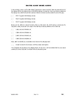
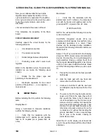
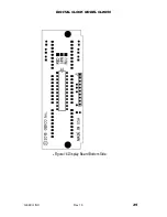
Figure 7: Main Board Top View 2
( )
C1: 22 pF (22) radial-lead ceramic
capacitor
( )
C2: 22 pF (22) radial-lead ceramic
capacitor
In the next step be sure to observe the correct
polarity as noted before and lay the capacitor
down against the board.
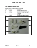
C3 SIDE VIEW
( )
C3: 10 uF radial-lead electrolytic
aluminum capacitor
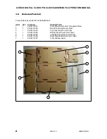
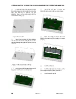
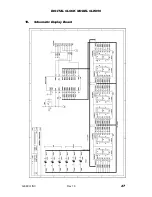
Figure 8: Main Board Top View 3
( )
Y1: Crystal HC49 16 MHz
For the next step, be careful to position the end
with the dot or line towards the “square pad”
and tapered outline on the circuit board. After
you solder the first pin make sure the pins are
fully seated in their holes, solder the rest of the
pins to the foil.
( )
RN1: 10 k
103 resistor pack.
NOTE: When you install the diode, be sure to
orient the diode correctly. Always match the
band on the diode with the band mark on the
circuit board. The circuit will not work properly if
a diode is installed backwards.
( )
D1: 1N5817 schottky diode
When installing the IC socket next, be sure to
align the notch on the socket with the notch on
the PCB silkscreen.
( )
X1: 28 pin DIP socket


