


GEKCO DIGITAL CLOCK P/N CLK056 ASSEMBLY & OPERATION MANUAL
16
REV 1.0
GEKCO INC.
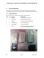
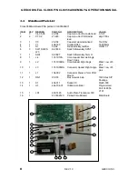
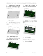
Now you can disassemble the two boards
together and set aside the two M3 x 12 mm
nylon standoffs to be used later. The four M3 x
6 mm nylon screws will not be used, if you plan
to use the acrylic enclosure, and can be
discarded.
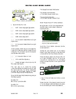
J5 is not installed in this version of the kit.
This completes the assembly of the Main
board.
CIRCUIT BOARD CHECKOUT
Carefully inspect the circuit boards for the
following problems.
( )
Unsoldered connections
( )
Poor solder connections
( )
Solder bridges between foil patterns
( )
Protruding leads which could touch
together
Refer to the illustration where the parts were
installed as you make the following visual
checks.
( )
Diodes for the proper type and
positioning of the banded end
( )
Electrolytic capacitors for the correct
position of the positive (
) or a negative (
)
marked ends
6.
Initial Tests
Before installing the IC’s perform the following
tests.
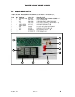
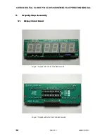
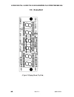
Display Board
Using a multi-meter to measure resistance
perform the following checks.
( )
Verify that the resistance with the
positive lead on C1 positive pin and negative
lead on C1 negative pin, is greater than 2k
ohms.
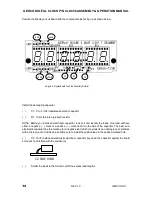
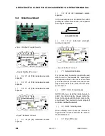
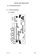
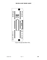
Main Board
( )
Verify that the resistance with the
positive lead on D1 cathode ( the component
end with the band) and negative lead on the
ground pad TP1, is greater than 2k ohms.
IC INSTALLATION.
NOTE: You will install the following IC’s on the
main circuit board.
CAUTION: Integrated circuits (IC’s) are
complex electrical devices that perform many
complicated operations in a circuit. These
devices can be damaged during installation.
Read all of the following information before you
install the IC’s.
Some of the IC’s you will install in the following
steps are MOS {metal oxide semiconductor)
devices. Be sure they do not get damaged by
static electricity. Once you remove the IC from
the foam pad,
do not let go of it
or lay it down
until it is in its socket. Install it as follows. Read
all of the following steps before you pick up an
IC.
1. Pick up the IC and touch the foam pad with
both hands.
2. Hold the foam pad with one hand and
remove the IC with the other hand.
3. Continue to hold the IC with the one hand
and straighten any bent pins with the other
hand.
4. The pins on
the IC’s may be bent out at an
angle, and if this is the case, they will not
line up with the holes in the IC socket or
circuit board pads. Lay the IC down on its
side as and very carefully roll it toward the
pins to bend the lower pins into line. Then
turn the IC over and bend the pins on the
other side in the same manner. Do not try
to install and IC without first bending the
pins as described. To do so may damage
the IC pins or the socket, causing an
intermittent contact.
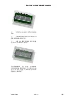
Install the IC on the display circuit board. Be
sure to line up the dimple with the circuit board
silkscreen


