

GEKCO DIGITAL CLOCK P/N CLK056 ASSEMBLY & OPERATION MANUAL
GEKCO INC.
Rev 1.0
1
TABLE OF CONTENTS
1.
INTRODUCTION ................................................................................................................................................ 3
2.
OPERATIONAL SUMMARY .......................................................................................................................... 3
3.
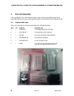
PARTS AND UNPACKING .............................................................................................................................. 4
3.1.
T
OP
L
EVEL
P
ARTS
L
IST
...................................................................................................................................... 4
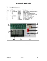
3.2.
D
ISPLAY
B
OARD
P
ARTS
L
IST
.............................................................................................................................. 5
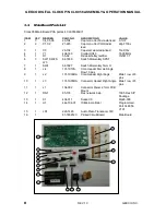
3.3.
M
AIN
B
OARD
P
ARTS
L
IST
................................................................................................................................... 6
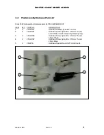
3.4.
F
INAL
A
SSEMBLY
H
ARDWARE
P
ARTS
L
IST
....................................................................................................... 7
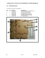
3.5.
E
NCLOSURE
P
ARTS
L
IST
..................................................................................................................................... 8
4.
ASSEMBLY NOTES ........................................................................................................................................... 9
4.1.
TOOLS ............................................................................................................................................................... 9
4.2.
ASSEMBLY ...................................................................................................................................................... 9
4.3.
SOLDERING ..................................................................................................................................................... 9
5.
STEP-BY-STEP ASSEMBLY ......................................................................................................................... 10
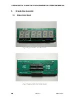
5.1.
D
ISPLAY
C
IRCUIT
B
OARD
................................................................................................................................. 10
5.2.
M
AIN
C
IRCUIT
B
OARD
...................................................................................................................................... 14
6.
INITIAL TESTS ................................................................................................................................................. 16
7.
FINAL TESTS .................................................................................................................................................... 17
8.
IN CASE OF DIFFICULTY ............................................................................................................................ 17
9.
FINAL PCA ASSEMBLY ................................................................................................................................ 17
10.
FINAL ASSEMBLY ...................................................................................................................................... 17
11.
THEORY OF OPERATION ....................................................................................................................... 20
11.1.
B
LOCK
D
IAGRAM
.............................................................................................................................................. 20
11.1.
M
AIN
B
OARD
C
IRCUIT
D
ESCRIPTION
............................................................................................................... 20
11.2.
D
ISPLAY
B
OARD
C
IRCUIT
D
ESCRIPTION
.......................................................................................................... 21
12.
FIRMWARE .................................................................................................................................................. 22
12.1.
F
LOW
C
HART
.................................................................................................................................................... 22
12.2.
F
IRMWARE
D
ESIGN
D
ESCRIPTION
.................................................................................................................... 23
13.
PCA PICTORIAL DIAGRAMS ................................................................................................................. 23
13.1.
M
AIN
B
OARD
.................................................................................................................................................... 23
13.2.
D
ISPLAY
B
OARD
............................................................................................................................................... 24
14.
SCHEMATIC MAIN BOARD .................................................................................................................... 26
15.
SCHEMATIC DISPLAY BOARD ............................................................................................................. 27
16.
DOCUMENT REVISION HISTORY........................................................................................................ 28