


DIGITAL CLOCK MODEL CLK056
GEKCO INC.
Rev 1.0
5
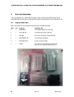
3.2.
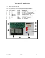
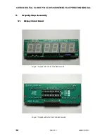
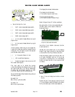
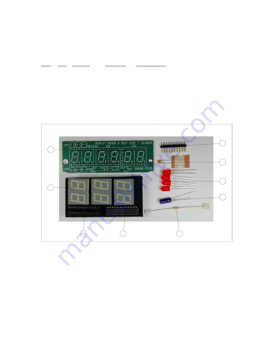
Display Board Parts List
Clock 056 Display Board Printed Circuit Assembly (PCA) parts kit, P/N DBR656-KIT
ITEM
QTY REFDES
PART NO.
DESCRIPTION
1
3
DS1,DS2,DS3 412-499
LED Display Module 7-Segment 2-Digit 0.56"
2
1
X1
434-3110
Socket IC Dip24-300
3
1
U1
442-3090
IC LED Display Driver MAX7219CNG
4
1
J1
131-1X10
Connector Header Single Row Male 10 pins
5
4
LED3,LED4,
LED5,LED6
412-125
LED Red PCB Mount T1 3/4
6
1
C2
26-102
Cap elect alum radial lead 10uF/16v
7
1
C1
20-104
Cap mono Cer 50v radial lead
8
1
R1
6-1002-12
Res metal film 1/4w 1% 10k
9
1
81-180911D
PCB Display Board
1
2
3
8
6
5
7
4
3


