24 / 32
1434 µPos
4
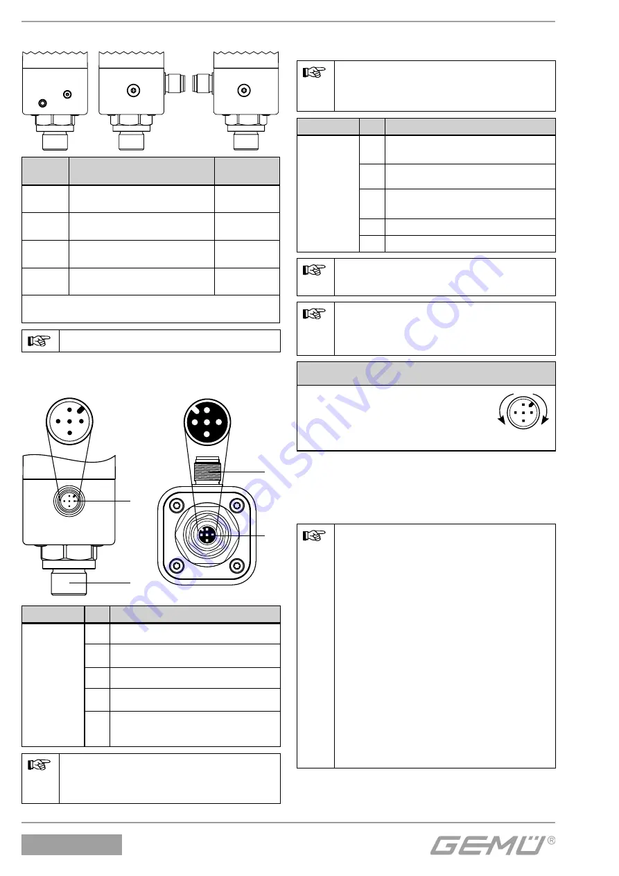
Pneumatic connections
1
2
3
E
Connec-
tion
Designation
Connection
size
1
Air supply connection P (max.
10 bar)
M5
2
Working connection for
process valve A1
M5
3
Venting connection R with
integrated check valve
M6 x 0.75*
E
Housing ventilation with
integrated check valve
M6 x 0.75*
* only relevant for exhaust air duct and/or increase of
protection class
Max.
air supply 8/10 bar!
5
Electrical connections
1
5
4
3
2
1
4
3
2
5
X1
X3
X1
X3
X1
X3
Connection Pin Signal name
X1
A-coded
M12 plug
1
U
v
, 24 V DC supply voltage
2
I+ / U+, 4-20 mA/0-20 mA/0-10 V
(set value input)
3
I- / U- GND
4
I+ / U+, 4-20 mA/0-20 mA/0-10 V
(actual value output – optional)
5
U
V
, initialisation 24 V DC,
initialisation is started by an impulse
signal t ≥ 100 ms
For connection cables >30 m,
take precautionary measures
against surge voltage.
In the version with external travel
sensor:
X3 is only required in
combination with an external
travel sensor system.
Connection Pin Signal name
X3
A-coded
M12 socket
1
UP+, output potentiometer supply
voltage (+)
2
UP, input potentiometer wiper
voltage
3
UP-, output potentiometer supply
voltage (-)
4
n. c.
5
n. c.
Earth the positioner housing
(using mounting bracket).
Take ESD protective
measures when mounting the
potentiometer.
CAUTION
Risk of cable break!
ä
Damage to the device.
● Turn electrical connections
max. 360°.
1
4
3
2
5
max. 360°
6
Initialisation and
commissioning
If the GEMÜ 1434 μPos is delivered
fully mounted to a valve ex works,
it is already preset at the factory
(at a control pressure of 5.5 – 6 bar
without operating pressure) and
is therefore ready for operation.
Reinitialisation (see chapter 7.2)
is recommended if the system is
operated under a diff erent control
pressure or if the mechanical end
positions have been changed (e.g.
seal replacement on the valve
or actuator replacement). The
initialisation is retained even in the
event of voltage cutoff .


