www.gemu-group.com
29 / 33
GEMÜ 1441 cPos-X
NOTICE
Exceptional maintenance work!
▶
Damage to the GEMÜ product.
●
Any maintenance work and repairs not described in these
operating instructions must not be performed without
consulting the manufacturer first.
The operator must carry out regular visual examination of the
products depending on the operating conditions and the po-
tential danger in order to prevent leakage and damage.
1. Have servicing and maintenance work performed by
trained personnel.
2. Wear appropriate protective gear as specified in plant op-
erator's guidelines.
3. Shut off plant or plant component.
4. Secure plant or plant component against recommission-
ing.
5. Depressurize the plant or plant component.
6. Actuate products which are always in the same position
four times a year.
16.1 Spare parts
CAUTION
Risk of explosion
▶
Explosion-protected versions (special function: code X)
must not be repaired. Any faulty explosion-protected ver-
sions must be replaced by a new device. The following
spare parts are only permitted for use in
non
explosion-
protected versions.
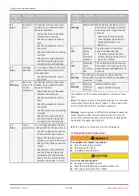
The following parts are available as spare parts:
Pilot valve module (four different versions: (single acting fail
safe/single acting fail freeze/double acting fail safe/double
acting fail freeze).
The pilot valve module must fit the device configuration in
question (check the reference on the controller's order data or
the details on the product label).
Action:
Code 1 = single acting fail safe:
Designation: 1441000EVM 1, order number: 88789910
Code 3 = double acting fail safe:
Designation: 1441000EVM 3, order number: 88789911
Code 5 = single acting fail freeze:
Designation: 1441000EVM 5, order number: 88789912
Code 6 = double acting fail freeze:
Designation: 1441000EVM 6, order number: 88789913
We recommend replacing the pilot valve module after a cer-
tain number of exceeded switching cycles.
The counter reading of the completed switching cycles can be
viewed via parameter S01: "Switching cycle counter" can be
read, and can be monitored via parameter S02: "Warning
threshold switching cycles" (if the counter reading exceeds
the set warning threshold, an alarm notification is generated).
Once the pilot valve module has been replaced, we recom-
mend resetting the switching cycle counter.
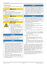
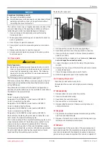
Replacing the spare part
1
2
1. Disconnect the product from the supply voltage.
2. Deactivate and disconnect the pneumatic connection.
3. Unscrew the four screws
1
in the rear black pneumatic
panel (Torx Tx20).
4. Carefully pull the complete unit out backwards (
take care
not to damage the connection cable
).
5. Loosen the plug-in contact to the side of the pilot valve
module.
6. Remove the four screws
2
that hold the pilot valve module
in place (Inbus Sw3).
7. Clean the support plate and check for faults.
8. Refit the replacement part in the reverse order.
16.2 Cleaning the product
- Clean the product with a damp cloth.
- Do
not
clean the product with a high pressure cleaning
device.
17 Disassembly
1. Disassemble in reverse order to assembly.
2. Unscrew the electrical wiring.
3. Deactivate the control medium.
4. Disconnect the control medium line(s).
5. Disassemble the product. Observe warning notes and
safety information.
18 Disposal
1. Pay attention to adhered residual material and gas diffu-
sion from penetrated media.
2. Dispose of all parts in accordance with the disposal regu-
lations/environmental protection laws.
19 Returns
Legal regulations for the protection of the environment and
personnel require that the completed and signed return deliv-
ery note is included with the dispatch documents. Returned
goods can be processed only when this note is completed. If
19 Returns


