www.gemu-group.com
14 / 33
GEMÜ 1441 cPos-X
8 Montage
NOTICE
Mounting bracket for mounting on level surfaces
▶
The GEMÜ 1441 000 ZMB mounting bracket, which is
available separately, can be used for this.
6. Electrically connect the travel sensor to the product.
7. Connect the product's pneumatic supply and connect the
product to the process valve.
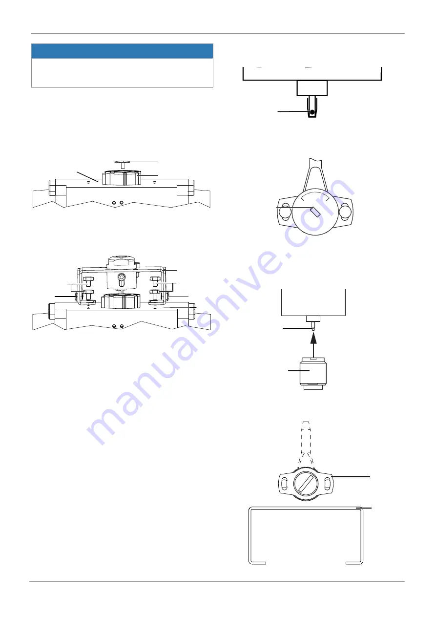
8.7 Preparations for installation of the valve (quarter
turn actuator)
1. Move the actuator
A
into zero position (actuator vented).
1
2
A
2. Remove the screw
1
from the trigger cam
2
.
8.8 Mounting kit assembly (quarter turn actuator) for
direct mounting
3
4
A
4
5
5
1. Adjust the mounting bracket to the required borehole pat-
tern.
ð
To do this, loosen the side screws
5
and set the retain-
ing feet onto the thread of the actuator, and install it
using screws
4
.
2. Secure the bracket
3
to the retaining feet as shown. In do-
ing so, the tap shaft must sit free of play in the shaft of the
actuator.
8.9 Mounting kit assembly (quarter turn actuator) for
remote mounting
2
1. The shaft of the rotary travel sensor is provided with a
marking
2
.
0
90
2
2. Set the marking
2
so that it is correctly aligned with the 0°
position on the underside of the travel sensor housing.
The 0° position is located on the left-hand side of the
cable exit (the electrical operating range is located in the
travel range between the 0° and 90° positions).
eco
OPEN
ERROR
CLOSED
POWER
2
4
3. Place the adapter
4
onto the shaft of the rotary travel
sensor
2
without twisting the shaft.
4
6


