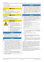
9 Pneumatic connection
CAUTION
▶
Observe the maximum control pressure of the actuator!
Connection in accordance with DIN
ISO 1219-1
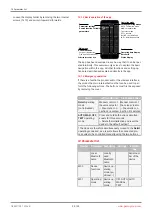
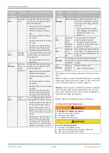
Designation
Size
1
Supply connection
G1/8 female thread
1)
3
Venting (with silencer)
G1/8 female thread
V1
Supply and exhaust air throttle for A1
-
V2
2)
Supply and exhaust air throttle for A2
-
2
Working connection (1) for process valve
(control function NC and NO)
G1/8 female thread
1)
4
2)
Working connection (2) for process valve
(control function DA)
G1/8 female thread
1)
1) The connections that are to be used are equipped with push-in fittings at the factory (depending on the order code for pneumatic lines 6/4
mm or 1/4“).
2) Only available for the double acting action (code 3 or 6).
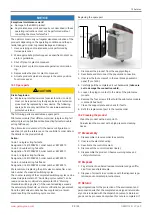
1. Establish the connection between the pneumatic output
2
(single acting) or connectors
2
and
4
(double acting) and the actu-
ator's pneumatic control air connector.
2. Connect the auxiliary power (supply air) to the air supply connection
1
(max. 7 bar/101 psi).
(V1)
(V2)
* Figure shows throttling (V1 and V2) in
the unthrottled position
GEMÜ 1441 cPos-X
www.gemu-group.com
17 / 33
9 Pneumatic connection


