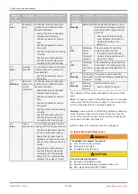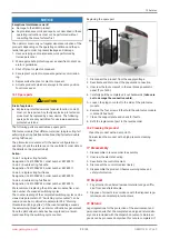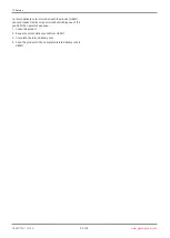
Description for using throttles V1 and V2
The throttle screw
V1
regulates the working connection's flow rate
A1
in both directions.
The throttle screw
V2
(only the double acting version) regulates the working connection's flow rate
A2
in both directions.
3. Activate the throttle function:
ð
Use a flathead screwdriver (maximum slot width 4 mm) to push the throttle in as far as it will go and turn clockwise by
approx. 120° (slot vertical = throttle position).
4. Deactivate the throttle function:
ð
Use a flathead screwdriver (maximum slot width 4 mm) to turn the throttle anticlockwise by approx. 120° and release
(slot approx. 45° = unthrottled position).
We recommend only using the throttle during initialization. The throttle(s) should be activated if operating times of <1.0
seconds have been determined or the control result is not satisfactory (for example, the control oscillates
→
reinitialization with
activated throttle). Experience has shown that operating times between 1 and 2 seconds lead to optimal control results.
9.1 General notes
CAUTION
Exhaust air and cycle duties generate noise
▶
Hearing damage
●
Wear hearing protection
The exhaust air connection is equipped with a silencer as standard to reduce noise emissions. Other commercially available si-
lencers with G1/8 male thread can also be fitted. Alternatively, the recessed G1/8 thread can be used to attach commercially
available pneumatic screw connections in order to be able to discharge the exhaust air in a targeted manner.
www.gemu-group.com
18 / 33
GEMÜ 1441 cPos-X
9 Pneumatic connection


