background image

www.gemu-group.com

26 / 33

GEMÜ 1441 cPos-X

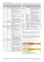
14 Parameter list

Number

Parameter Description Settings

Initial set-

ting

P17

Set value

limit OPEN

Upper

range of

the set

value limit

0 to 100% 0%

P18

Close tight

function

CLOSED

Lower

range of

the close

tight func-

tion

0.0 to

20.0%

0.5%

P19

Close tight

function

OPEN

Upper

range of

the close

tight func-

tion

80.0 to

100.0%

99.5%

P01

Split range

start

Starting

point of the

split-range

function

0.0 to

90.0%

0.0%

P02

Split range

end

End point

of the split-

range func-

tion

10.0 to

100.0%

100.0%

P15

Set value

direction of

action

Inversion

of the tar-

get value

signal

rise, fall

rise

P14

Control

curve

The control

curve is

defined

Linear,

1:25, 1:50,

free

Linear

P03

Character-

istic curve

point 0%

Calibration

point 0 of

the free

character-

istic

0.0 to

100.0%

0.0%

P04

Character-

istic curve

point 10%

Calibration

point 10 of

the free

character-

istic

0.0 to

100.0%

10.0%

P05

Character-

istic curve

point 20%

Calibration

point 20 of

the free

character-

istic

0.0 to

100.0%

20.0%

P06

Character-

istic curve

point 30%

Calibration

point 30 of

the free

character-

istic

0.0 to

100.0%

30.0%

P07

Character-

istic curve

point 40%

Calibration

point 40 of

the free

character-

istic

0.0 to

100.0%

40.0%

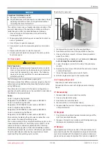
Number

Parameter Description Settings

Initial set-

ting

P08

Character-

istic curve

point 50%

Calibration

point 50 of

the free

character-

istic

0.0 to

100.0%

50.0%

P09

Character-

istic curve

point 60%

Calibration

point 60 of

the free

character-

istic

0.0 to

100.0%

60.0%

P10

Character-

istic curve

point 70%

Calibration

point 70 of

the free

character-

istic

0.0 to

100.0%

70.0%

P11

Character-

istic curve

point 80%

Calibration

point 80 of

the free

character-

istic

0.0 to

100.0%

80.0%

P12

Character-

istic curve

point 90%

Calibration

point 90 of

the free

character-

istic

0.0 to

100.0%

90.0%

P13

Character-

istic curve

point 100%

Calibration

point 100

of the free

character-

istic

0.0 to

100.0%

100.0%

P36

Error posi-

tion

Valve posi-

tion at er-

ror mes-

sage

Close,

Open, Hold,

Safe

Close

P27

Control

function

Control

function of

the pro-

cess valve

P37

Error time Debounce

time of er-

ror mes-

sages

0.2 to

100.0 s

0.2 s

P38

Set value I

min

Switch-off

limit for

cable break

recognition

of the set

value

0.0 to 22.0

mA

3.5 mA

P39

Set value I

max

Switch-off

limit for ex-

cess cur-

rent recog-

nition of

the set

value

0.0 to 22.0

mA

20.5 mA

Summary of Contents for 1441 cPos-X

Page 1: ...GEMÜ 1441 cPos X Intelligent electro pneumatic positioner Operating instructions EN further information webcode GW 1441 ...

Page 2: ...hts including copyrights or industrial property rights are expressly reserved Keep the document for future reference GEMÜ Gebr Müller Apparatebau GmbH Co KG 05 05 2022 www gemu group com 2 33 GEMÜ 1441 cPos X ...

Page 3: ... g seal replacement or actuator replacement 1 Mount the product on the process valve mechanically using the mounting kit 2 Connect the product pneumatically ð Supply the connector 1 with pneumatic auxiliary power max 7 bar observe the process valve s max control pressure ð Connect the connector 2 to the process valve s control air connector on double acting valves connect connector 4 to the second...

Page 4: ...ation of the valve quarter turn actuator 14 8 9 Mounting kit assembly quarter turn actu ator for remote mounting 14 8 10 Direct mounting to quarter turn actuators 15 8 11 Remote mounting to quarter turn actuators 15 8 12 Checking the mechanical mounting 16 9 Pneumatic connection 17 9 1 General notes 18 10 Electrical connection 19 10 1 Electrical connection with M12 19 10 2 Electrical connection wi...

Page 5: ...ure causes the GEMÜ product to be actuated and operated Speed AP function Speed Assembly and Programming a particularly user friendly commissioning function for fast mounting automated setting and initialization of GEMÜ products Dependent on type activation uses an external impulse signal or existing precautions on the device magnetic or housing switch Changeover to normal operating mode takes pla...

Page 6: ...cument 12 Operate the product in accordance with the specifications 13 Maintain the product correctly 14 Do not carry out any maintenance work and repairs not de scribed in this document without consulting the manufac turer first In cases of uncertainty 15 Consult the nearest GEMÜ sales office 4 Product description 4 1 Construction 2 3 4 C 1 Item Name Materials 1 Housing cover Grivory PA 6 6 2 Ins...

Page 7: ...e app 4 5 Fail safe function The product has a fail safe function which switches the out puts in a controlled manner if the pneumatic air supply or the electrical supply voltage fails see Fail safe functions page 21 This fail safe function does not replace the re quired plant specific safety devices The product is not a safety controller 5 Correct use WARNING Improper use of the product Risk of se...

Page 8: ... rate 115 Nl min 25 C 6 5 bar Air consumption 0 05 Nl min when idle 6 4 Product compliance EMC Directive 2014 30 EU Technical standards used Interference emission DIN EN 61000 6 3 2007 A1 2011 AC 2012 DIN EN 61326 1 industry 07 2013 Interference resistance EN IEC 61000 6 1 2019 EN 61326 1 2013 industry Class B Group 1 Radio Equipment Direct ive RED 2014 53 EU Technical standards used Standard rega...

Page 9: ...idity Maximum 95 non condensing Protection class IP 65 acc to EN 60529 Degree of contamination 3 pollution degree 6 7 Electrical data 6 7 1 Power supply set value input Supply voltage Via set value signal Note A voltage of 30 V DC and an input current of 100 mA must not be exceeded In total a power of 1 W must not be exceeded Power consumption 0 3 W Short circuit proof Yes Set value input 4 20 mA ...

Page 10: ...V DC 7 30 V DC Output type passive Logic level 1 conductive Logic level 0 disabled 6 7 5 Travel sensor input for travel length code S01 remote potentiometer Note Travel sensor input is not galvanically isolated from the supply voltage set value input Input voltage range 0 to UP Supply voltage UP Typically 0 48 V DC Resistance range of re mote potentiometers 1 8 6 kΩ ideal 5 kΩ 20 6 7 6 Positioner ...

Page 11: ...zone 1 default setting 0 1 25 0 can be set at fixed values 0 1 25 0 adaptive self adjustment Parameterization Via app or HART Initialization Automatic via magnetic switch app digital input or HART Close tight function Closed W 0 5 Open W 99 5 can be changed via the app Interface Bluetooth Low Energy HART Function Parameterization configuring diagnostics Parameterization configuring diagnostics Dev...

Page 12: ...aintained to ensure that the unit can be disas sembled at any time The rear pressure balance openings right hand figures 1 must be maintained in the event of a malfunction targeted venting of the housing is guaranteed by the pressure balance openings 8 2 Preparations for mounting to the valve 1 Move the actuator A into zero position actuator vented 2 Remove optical position indicator 2 and or prot...

Page 13: ...tic supply and connect the product to the process valve NOTICE Damage to internal stop Do not mount the product by turning the internal stop If correctly mounted to the corresponding valve the product can be turned 320 8 6 Remote mounting to linear actuators 1 2 3 4 3 WAF 27 1 Mount the travel sensor mounting kit see Linear travel sensor mounting kit assembly for remote mounting page 12 2 Move the...

Page 14: ...uired borehole pat tern ð To do this loosen the side screws 5 and set the retain ing feet onto the thread of the actuator and install it using screws 4 2 Secure the bracket 3 to the retaining feet as shown In do ing so the tap shaft must sit free of play in the shaft of the actuator 8 9 Mounting kit assembly quarter turn actuator for remote mounting 2 1 The shaft of the rotary travel sensor is pro...

Page 15: ...1 Mount the travel sensor mounting kit on the product see Linear travel sensor mounting kit assembly for remote mounting page 12 2 Use the mounted mounting kit to screw the product 1 onto the adapter 4 3 Use the spanner flat 8 WAF 27 of the travel sensor to tighten the product 1 4 Turn the housing clockwise to align the pneumatic or elec trical connections 5 Connect the product s pneumatic supply ...

Page 16: ...e available as accessories for this Depending on the desired version the product can therefore be mounted on level surfaces or on walls NOTICE Mounting bracket for wall mounting The GEMÜ 1441 000 ZMP mounting bracket which is available separately can be used for this NOTICE Mounting bracket for mounting on level surfaces The GEMÜ 1441 000 ZMB mounting bracket which is available separately can be u...

Page 17: ...s valve control function DA G1 8 female thread1 1 The connections that are to be used are equipped with push in fittings at the factory depending on the order code for pneumatic lines 6 4 mm or 1 4 2 Only available for the double acting action code 3 or 6 1 Establish the connection between the pneumatic output 2 single acting or connectors 2 and 4 double acting and the actu ator s pneumatic contro...

Page 18: ...rottle during initialization The throttle s should be activated if operating times of 1 0 seconds have been determined or the control result is not satisfactory for example the control oscillates reinitialization with activated throttle Experience has shown that operating times between 1 and 2 seconds lead to optimal control results 9 1 General notes CAUTION Exhaust air and cycle duties generate n...

Page 19: ... 4 20 mA current loop opt HART 2 Iw set value input 4 20 mA current loop opt HART 3 n c 4 Iout actual value output 4 20 mA no internal supply passive 5 Iout actual value output 4 20 mA no internal supply passive Connection X3 1 5 4 3 2 5 pin M12 plug B coded Pin Signal name 1 DigIn 2 DigIn 3 n c 4 DigOut 5 DigOut GEMÜ 1441 cPos X www gemu group com 19 33 10 Electrical connection ...

Page 20: ...le gland Recommended cable diameter EX protected version blue cable gland 7 9 mm Non EX protected version black cable gland 4 10 mm Wire cross section 0 5 2 5 mm AWG 20 to 12 IW AO DI DO Terminal Terminal label Terminal name Signal name 1 IW Iw Iw set value input 4 20 mA cur rent loop opt HART 2 IW Iw Iw set value input 4 20 mA current loop opt HART 3 AO Iout Iout actual value output 4 20 mA no in...

Page 21: ...e Blocking However the fail safe function does not replace the plant specific safety devices Adjustable safety reactions Error Connection A1 2 Connection A2 4 Set value 4 mA range below the set value under I Min W can be adjusted 0 22 mA Single and double acting Adjustable function Open Close Hold Safe Single acting Connection not available Double acting Adjustable function Open Close Hold Safe Se...

Page 22: ...valve at the factory the complete construction is already ready for op eration at a control pressure of 5 5 to 6 bar without oper ating pressure A reinitialization is recommended if the plant is operated with a different control pressure or if the mechanical end positions have been changed e g seal replacement on the valve or actuator replacement The initialization is retained even in the event of...

Page 23: ...diately after the product has been electrically connected When delivered the product is protected against unauthorized access using a unique connection password The password matches the digital product label QR code that is affixed on the product To enter the password this can be read using the camera scan function on the smartphone tablet or entered manually The password can be managed independen...

Page 24: ...on If there is a fault in the product and or the wireless interface the product has two internal buttons that can be used to per form the following actions The buttons must first be exposed by removing the cover Status Left hand button Right hand button NoInit operating mode not initialized Manual control of the valve actuator Pneumatic con nection 2 is vented Manual control of the valve actuator ...

Page 25: ...dead zone 0 1 to 25 0 1 0 P44 Dead zone value auto Dead zone value auto 0 1 to 25 1 is ad justed automatic ally P24 Dead zones func tion Automatic dead zone adjustment manual auto manual Number Parameter Description Settings Initial set ting Set value manual Current set value for manual op eration 0 0 to 100 0 S06 1 Set value Compar ison of set value and valve posi tion 0 0 to 100 0 S06 2 Valve po...

Page 26: ...0 of the free character istic 0 0 to 100 0 30 0 P07 Character istic curve point 40 Calibration point 40 of the free character istic 0 0 to 100 0 40 0 Number Parameter Description Settings Initial set ting P08 Character istic curve point 50 Calibration point 50 of the free character istic 0 0 to 100 0 50 0 P09 Character istic curve point 60 Calibration point 60 of the free character istic 0 0 to 10...

Page 27: ...ax Upper switch point of the digital out put 0 2 to 99 8 90 0 Number Parameter Description Settings Initial set ting S08 Status di gital output Status of digital out put S12 Active parameter set Displays the active parameter set P1 P2 P1 P25 Copying parameter set Copy to dif ferent memories off P1 W P1 P2 P1 P2 off P28 Initializa tion start via magnet Initializa tion option via magnet contact P41 ...

Page 28: ...bly on the valve is correct Message ID and type Description Cause and remedial measures 61 Warning Button fault While starting the device one or both internal emergency buttons were pressed for longer than 60 seconds Check whether the housing cover actuates the buttons or whether the buttons are jammed 70 Info Switching cycles alarm threshold reached The set number of switching cycles has been rea...

Page 29: ...eze Designation 1441000EVM 6 order number 88789913 We recommend replacing the pilot valve module after a cer tain number of exceeded switching cycles The counter reading of the completed switching cycles can be viewed via parameter S01 Switching cycle counter can be read and can be monitored via parameter S02 Warning threshold switching cycles if the counter reading exceeds the set warning thresho...

Page 30: ...luded with the product GEMÜ cannot process credits or repair work but will dispose of the goods at the operator s expense 1 Clean the product 2 Request a return delivery note from GEMÜ 3 Complete the return delivery note 4 Send the product with a completed return delivery note to GEMÜ ...

Page 31: ...2 1 5 6 1 5 8 1 5 16 1 6 1 Technical standard used in parts ISO 12100 We also declare that the specific technical documentation has been compiled in accordance with part B of Annex VII The manufacturer or their authorised representative undertakes to transmit in response to a reasoned request relevant documents on the partly completed machinery to the national authorities This transmission takes p...

Page 32: ... Directive 2014 53 EU RED Directive 2014 53 EU Product GEMÜ 1441 Product name Intelligent electro pneumatic positioner The Essential Safety and Health Requirements are met by compliance with the standards used in parts listed below that are applicable for the above mentioned product EN 61326 1 2013 EN IEC 61000 6 1 2019 EN 61000 6 3 2007 A1 2011 AC 2012 EN 61010 1 2010 A1 2019 AC 2019 04 EN 300 32...

Page 33: ...GEMÜ Gebr Müller Apparatebau GmbH Co KG Fritz Müller Straße 6 8 74653 Ingelfingen Criesbach Germany Phone 49 0 7940 1230 info gemue de www gemu group com Subject to alteration 05 2022 88796116 ...

Reviews: