Rev. 00 03/19
OptiFlex Pro B
OptiFlow IG07
57
OptiFlow IG07
For further information, see the corresponding operating manual,
which can be found on the accompanying CD.
Structure
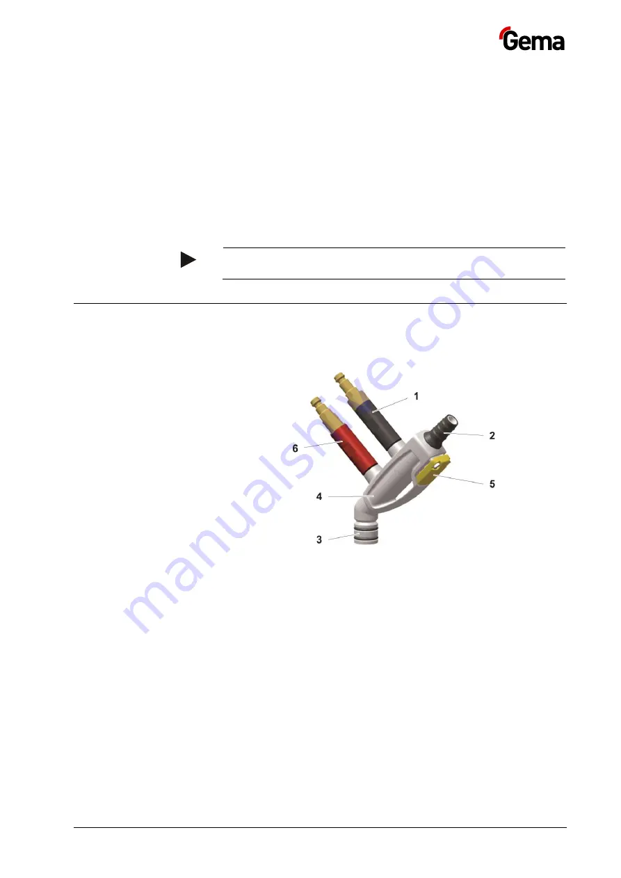
Overall view
Fig. 14
1
Check valve unit
(supplementary air)
2
Powder hose quick release
connection
3
Powder hopper connection
4
Injector housing
5
Release trigger
6
Check valve unit
(conveying air)
Summary of Contents for OptiFlex Pro B
Page 12: ...Rev 00 03 19 12 Safety OptiFlex Pro B ...
Page 34: ...Rev 00 03 19 34 Operation OptiFlex Pro B ...
Page 36: ...Rev 00 03 19 36 Decommissioning Storage OptiFlex Pro B ...
Page 50: ...Rev 00 03 19 50 Fault clearance OptiFlex Pro B ...
Page 54: ...Rev 00 03 19 54 OptiSelect Pro GM04 OptiFlex Pro B ...
Page 62: ...Rev 00 03 19 62 Maintenance Repairs OptiFlex Pro B ...
Page 64: ...Rev 00 03 19 64 Fault clearance OptiFlex Pro B ...
Page 67: ...Rev 00 03 19 OptiFlex Pro B Spare parts list 67 OptiFlex Pro B Spare parts fig 17 ...
Page 75: ...Rev 00 03 19 OptiFlex Pro B Spare parts list 75 Inside back plate fig 23 OptiStar CG21 ...
Page 77: ...Rev 00 03 19 OptiFlex Pro B Spare parts list 77 Connecting material fig 24 ...
Page 88: ...Rev 00 03 19 88 Spare parts list OptiFlex Pro B OptiFlow IG07 spare parts fig 28 ...
Page 90: ...Rev 00 ...


