BGS2-E Release Notes
Confidential / Released
BGS2-E_rn_v01.301c
Page 12 of 12
2012-02-08
R2
2
2
3
2
1
X201
3
2
1
X210
V143
C101
C102
X305
X307
X308
X309
2
4
1
3
X311
80
70
60
50
41
40
30
2
0
10
1
X100
2
14
13
1
2
14
13
1
2
14
13
1
J
P
BG2-DSB75 adapter
80
79
2 1
X135
31
30
60
1
1
J
P
J
P
J
P
C
CRS
T
CC
VCC
CC
IO
CCC
LK
CC
IN
GND
GND
I2CCLK
GND
GPIO7
GPIO5
GPIO3
GPIO1
GN
D
A
DC1
AG
ND
PW
R
_
IN
D
VDIGD
I2
CD
A
T
GPIO
8
GPIO
6
GPIO
4
GPIO
2
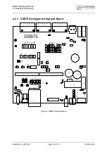
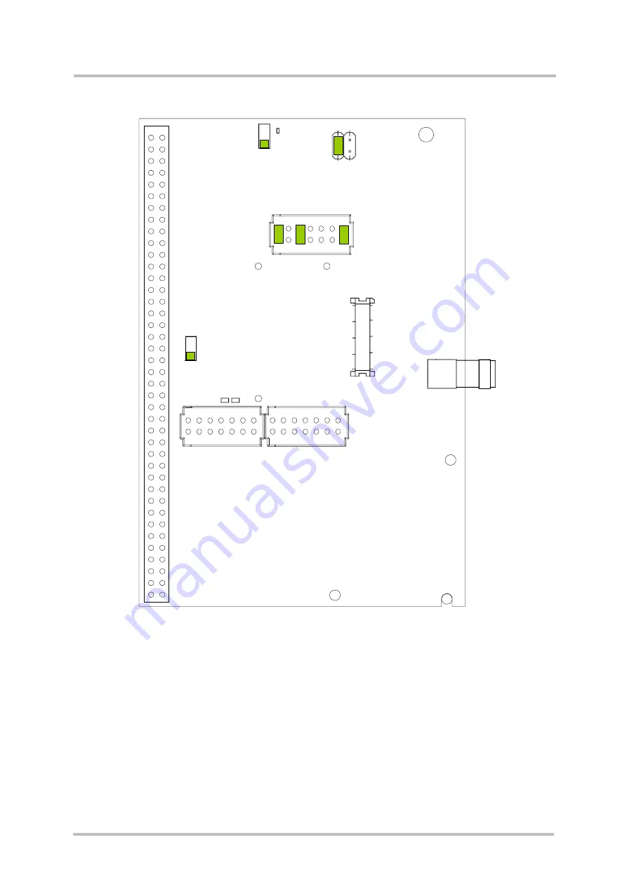
Figure 4: BG2-DSB75 Adapter (overview)
Note: The PWR_IND signal is generated by a power indication circuit integrated on the BGS-
DSB75 Adapter, similar to the power indication circuit recommended in [1] for the final
product. The PWR_IND signal notifies the on/off state of the connected module. If the
module is switched on the PWR_IND signal switches on the DSB75.


