BGS2-E Release Notes
Confidential / Released
BGS2-E_rn_v01.301c
Page 8 of 12
2012-02-08
4
Getting Started with BGS2-E
For testing and debugging purposes BGS2-E is supplied as an evaluation module. The
evaluation module comprises of the actual SMT module soldered onto a PCB with a 60-pin
board-to-board connector on its bottom side that can be connected to Cinterion’s
Development Support Board DSB75
.
DSB75 is an evaluation kit designed for a wide range of Cinterion wireless modules. It pro-
vides an application interface between the module and a PC. A detailed DSB75 interface
description and operating instructions can be found in [4]. The focus of this chapter is only on
how to operate a BGS2-E evaluation module at a DSB75.
4.1 Technical Requirements
BGS2-E evaluation module, Revision 01.301
DSB75 Development Support Board
BG2-DSB75 Adapter required for mounting the evaluation module to the DSB75.
Accessories:
-
External 50 Ohms RF antenna connecting to the SMA connector on the BG2-DSB75
Adapter (e.g. a SMARTEQ MiniMag antenna such as delivered with each DSB75
Development Support Board)
-
9 to 15 Volts power supply applied at the DSB75 for powering up the DSB75 and the
connected BGS2-E module (not supplied by Cinterion)
-
Optional: Votronic Handset (delivered with each DSB75)
-
RS-232 cables for the module’s asynchronous serial interfaces ASC0 and ASC1
Appropriate application for controlling the module from within Windows, e.g. Windows
Hyperterminal
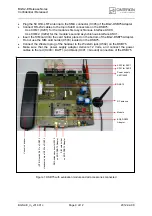
4.2 Connecting the BGS2-E Evaluation Module to DSB75
To properly connect the BGS2-E evaluation module and all accessories to the DSB75 follow
the steps listed below.
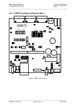
Prepare the DSB75 as shown in
:
-
Ensure that all jumpers and slide switches marked green are correctly set on your
DSB75 (i.e., factory default settings except for S730 and S731).
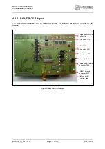
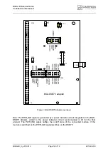
Prepare the BG2-DSB75 Adapter as shown in
:
-
Ensure that the four jumpers and the slide switches X201 and X210 are set to the
default positions marked green.
Attach the 80-pin header (X135) of the BG2-DSB75 Adapter to the 2x40-pin header
(X101/X202) located on the DSB75. Take gentle care that all pins are aligned correctly,
then press down evenly on the adapter until it is firmly seated.
Mount the BGS2-E evaluation module onto the 60-pin board-to-board connector (X100)
located on the BG2-DSB75 Adapter.
1
A specialized SMT Socket provides a further possibility for testing and debugging SMT modules
during development. The SMT Socket allows multiple connect/disconnect cycles and eliminates the
need of soldering your test samples. A detailed description of how to get started using the SMT
Socket is not yet available.


