background image


Page 18


Verifying the USB Driver Installation 

1.


Right

-

click


on 

My Computer

 and click on 

Properties

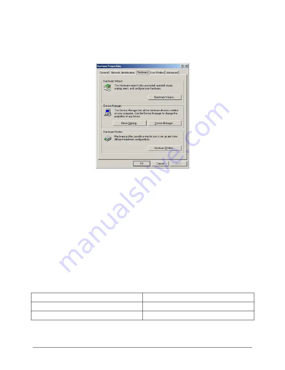
The 

System Properties

 window opens. 

Figure 13: System Properties window 


2.


Click on the 

Hardware

 tab, then on 

Device Manager

The 

Device Manager

 window opens. 

3.


Expand (click on the plus sign) the entry called 

Smart Card Readers

4.


Verify that there are entries for the USB SmartCard and USB Contactless Readers 
(ePassport option only). 

Note:


If you cannot verify that the drivers have been properly installed, turn the reader 
off and back on and try the installation again. If verification still fails, contact 
Gemalto Global Technical Services (GTS).  
For more information, see Appendix D: Customer Service on page 29. 

Power-up Self Test 

A power-up self-test occurs automatically when the reader powers up. If the reader is installed 
correctly and is operational, the status LEDs perform the following sequence: 


All LEDs come ON briefly at initial power-up. 


After several seconds the green LED (READY) remains ON, and all other LEDs go OFF. 

The LEDs may also indicate the following common communication errors: 

LED Behaviour 

Meaning 

The Ready LED flashes rapidly 

No USB connection detected 

The Ready and Error LEDs flash rapidly 

USB 1.1 connection detected 

Note:


The reader will not transfer document images over a USB 1.1 host connection. 
However, RFID chip reading (ePassport option only) and any USB 1.1 
peripherals attached to the reader will function over a USB 1.1 host connection. 

Summary of Contents for Kiosk ePassport Reader PV35-02-17-00-01

Page 1: ...Kiosk ePassport Reader User Guide Document DT 01822 Revision E Date June 2017 ...

Page 2: ...ill meet Gemalto s written specifications at the time of shipment Gemalto s obligation and your exclusive remedy shall be at Gemalto s option to replace or repair the Gemalto Product or refund the purchase price of the Gemalto Product IN NO EVENT WILL GEMALTO BE LIABLE FOR ANY INDIRECT INCIDENTAL SPECIAL OR CONSEQUENTIAL DAMAGES INCLUDING BUT NOT LIMITED TO LOSS OF PROFITS IN ANY WAY RELATED TO TH...

Page 3: ...ets the following European Council Directives Scanner EMC 2004 108 EC RFID Option RE TTE 1999 5 EC PSU EMC 2004 108 EC LVD 2006 95 EC FCC Canada Radio Frequency Rules and Regulations This equipment has been tested and found to comply with the limits for a Class A digital device pursuant to Part 15 of the FCC Rules These limits are designed to provide a reasonable protection against harmful interfe...

Page 4: ...accept any interference including interference that may cause undesired operation of the device Le présent appareil est conforme aux CNR d Industrie Canada applicables aux appareils radio exempts de licence L exploitation est autorisée aux deux conditions suivantes 1 l appareil ne doit pas produire de brouillage et 2 l utilisateur de l appareil doit accepter tout brouillage radioélectrique subi mê...

Page 5: ... and Window 7 Back Panel 8 USB Ports 8 Status Indicator LED s 8 Power Connector 9 Mounting Points 9 Installing the Hardware 11 Unpacking the Reader 11 Kiosk Design Considerations 11 Connecting the Power Supply 13 Connecting to the Host System 13 Installing the software 15 Verifying the USB Driver Installation 18 Power up Self Test 18 Testing Reading and Communication 19 Reading Procedure 20 Mainte...

Page 6: ...Page vi Windows 2000 27 Windows XP 28 Chipset Updating 28 Appendix D Customer Service 29 Before contacting GTS 29 Contacting GTS 29 Returning the reader for maintenance 30 ...

Page 7: ...el documents on the glass imaging surface It has not been evaluated for other uses such as stand alone desktop use or other environmental conditions Explanation of Product Safety Label Symbols Warning Indoor Dry Location Use Only Attention Refer to Instructions The Waste Electrical and Electronic Equipment Directive WEEE Directive is the European Community directive 2012 19 EU on waste electrical ...

Page 8: ...ser serviceable parts or adjustments inside Do not use AC power supply and or power cord if damaged Product is to be serviced by Gemalto service personnel only No user serviceable parts or adjustments inside Do not modify or attempt to modify the reader and or AC power supply Use only in an indoor dry location Do not use the product in an outdoor and or wet environment CAUTION Dispose of electroni...

Page 9: ...rcodes customized client requirements Extended Access Control EAC 1 01 specification support document rotation detection and processing support contactless integrated circuit IC chips optional The readers capture full page document images using Visible color illumination Near infrared B900 band illumination Ultra violet illumination The readers perform optical character recognition on identity doc...

Page 10: ...t Images The following are examples of infrared visible and ultra violet imaging Figure 1 Infrared Image Figure 2 Visible Image Figure 3 Ultra Violet Image Related Documents The range of applications for reading and authenticating secure documents is growing Particularly with the development and deployment of ePassports and smart identity cards authentication has become critical to security Gemalt...

Page 11: ...s a data group from the card embedded in the travel document The entire data group is returned in the data buffer DT 01762 Logical Data Structure Skin API Specification Facilitates the manipulation of data found on ePassports Sample Function unsigned long MMM_LDS_ValidActiveAuthenticationSignature verifies the digital signature returned from a radio frequency RF chip in response to an active authe...

Page 12: ...Page 6 retrieve USB data streams decode and access data images ...

Page 13: ...ent Tray and Window The document window is a glass surface measuring 132mm x 88mm located on top of the reader Users place documents on the document tray imaging side down and slide them to the back of the document window to scan them Guides on the document tray help align the document and keep it pressed onto the glass window The document window is slightly larger than ICAO 9303 requirements to a...

Page 14: ... etc The two USB peripheral connectors are capable of supplying 5V DC at a total of 500mA to the peripherals e g 500mA to a single peripheral 250mA to each of two peripherals etc Status Indicator LED s The status LEDs are intended to assist a technician to install and debug the reader and indicate the reader status and the result of scanning a document They are not visible by a user Table 1 Indica...

Page 15: ...ector The reader must be connected to a Underwriters Laboratory UL Listed DC power supply capable of providing 12V DC at 1 1A The connector pinouts are shown in the following figure Figure 7 Power Supply Connector Mounting Points The readers contain eight M4 threaded mounting bosses two on each side and four on the bottom as shown in the following figure The preferred mounting points are on the bo...

Page 16: ...Page 10 Figure 8 Mounting Mechanical Detail ...

Page 17: ...Considerations The reader is designed to be mounted behind the kiosk front panel with only the document tray protruding The front panel must provide an opening to allow users to insert their documents and hold them flat on the document glass for scanning The opening should form a box open at the front and closed at the top sides and back To better illustrate this a typical kiosk concept is shown i...

Page 18: ...e reader and its threaded mounting points When designing a kiosk to accommodate the reader consider the following factors Attach the reader using the bottom attachment points if possible In ePassport models keep metallic surfaces away from the document tray and document glass These areas contain the radio frequency identification RFID antenna and RF reading can be disrupted by the presence of meta...

Page 19: ...ot Recommended Note The reader should be inclined 5 to 10 to prevent liquid from entering the kiosk and to discourage its use as a shelf Connecting the Power Supply The reader is designed to be powered from a switched UL listed power source supplied with the kiosk and terminating in a suitable DIN connector The reader is supplied with a power cable and power supply but does not have a power switch...

Page 20: ...e USB connector of the supplied cable into a USB port on the host system 2 Insert the USB connector of the supplied cable into the USB port located on the back panel of the reader 3 Secure or tie off the cable as required ...

Page 21: ...ware 1 Download the latest SDK software from the provided link Click on the Gemalto Page Reader SDK x x x Setup exe link and save the exe file to a known location on the host PC for example the desktop 2 Run the downloaded exe file The installation wizard starts 3 Click Next to proceed with the installation The software license is displayed 4 If you accept the License Agreement select I accept the...

Page 22: ...ible to all users or just yourself 7 Click Next to proceed with the installation 8 The Select Components screen is displayed Click Typical 9 Select the shortcuts that the installation should create 10 Click Next The Ready To Install window is displayed ...

Page 23: ...eader device drivers is displayed 12 Review the installation notes for any specific instructions 13 Click Next to proceed with the installation The device drivers are installed After the driver installation the final installation page will be displayed 14 Click Finish The installation of the software and drivers is complete ...

Page 24: ...ices GTS For more information see Appendix D Customer Service on page 29 Power up Self Test A power up self test occurs automatically when the reader powers up If the reader is installed correctly and is operational the status LEDs perform the following sequence All LEDs come ON briefly at initial power up After several seconds the green LED READY remains ON and all other LEDs go OFF The LEDs may ...

Page 25: ...g OCR data as well as a programmed contactless chip Readers without the ePassport option are supplied with test card DS 00034 containing only OCR data 6 Place the test card face down on the document tray Note For best reading results align the document with the left guide 7 Push the card to the back of the document window until it stops Note Do not move the document during the scanning process 8 O...

Page 26: ...he proper document placement for travel document booklets Note Hold the document open as you place it into the document slot 1 Place the booklet on the document platform Figure 15 Reading Procedure Document Placement Note You may want to use two hands to insert the document into the reader ...

Page 27: ...nt reaches its proper position the reader will automatically start scanning the document Note Make sure the document lies flat against the document platform during reading 3 Watch the kiosk screen to ensure the document passes inspection Figure 17 Reading Procedure Inspection Results Travel document fully inserted Inspection results displayed on screen ...

Page 28: ...d To reorder cleaning cloths part number 70071086394 contact Gemalto Global Technical Services GTS See Appendix D Customer Service on page 29 for more information 1 Clean the document window with a clean cloth For dirt use a mild glass cleaner or a lightly dampened cloth water Note Do not use abrasive cleaners or solvents These may scratch the glass or damage the plastic Do not used compressed air...

Page 29: ...IN Table 4 Environmental Specifications Temperature Operating 0 40 C 32 104 F Storage 20 50 C 4 122 F Humidity Operating 20 80 non condensing Storage 5 95 non condensing Table 5 Communication Interfaces and Protocols Connection Interface USB 2 0 480 Mbit s High Speed Host USB Power Reader draws no power from host USB connector USB connector USB B host USB A x 2 peripherals USB cable length 2 00 m ...

Page 30: ...EA EN55024 EMC EMC ESTI EN 301 489 1 V1 6 1 2005 09 EMC ESTI EN 301 489 3 V1 4 1 2002 08 EMC ESTI EN 300 330 1 V1 5 1 2006 04 EMC ESTI EN 300 330 2 V1 3 1 2006 04 EN50364 Limitation of human exposure to electromagnetic fields from devices operating in the frequency range 0 Hz to 10 GHz used in electronic article surveillance EAS radio frequency identification RFID and similar applications ...

Page 31: ...erify that only one reader is connected to the host system Follow the procedure outlined in Chipset Updating on page 28 The Error LED illuminates when a document is scanned The document is non machine readable This is a normal condition when there is no machine readable data and only the image is captured from the document The document is poorly printed The reader is designed to read documents tha...

Page 32: ...n is running Remove the existing application re install software For more information see the Software Installation section You do not have PC Administrative rights to install the software Consult with your IT support representative The LEDs do not change after reading an RF chip Normal This is a normal condition RF status is displayed only on the host screen The reader becomes unresponsive Depend...

Page 33: ...ct Gemalto Global Technical Services GTS See Appendix D Customer Service on page 29 Windows 2000 1 In Windows 2000 right click My Computer and select Properties Figure 19 System Properties window 2 Locate the version number on the General tab and verify that Service Pack 4 or greater has been installed 3 Right click My Computer and select Manage 4 Click on Device Manager in the Tree list 5 Under U...

Page 34: ...speed USB 2 0 capability Chipset Updating The Check for High Speed USB 2 0 process determines if the PC has the correct hardware Chipset updating ensures that the PC also has the correct driver software for that hardware The program chipid exe is used to determine your chipset It is available in the install directory on your system following installation If the workstation uses the Intel USB chips...

Page 35: ... detailed description of the actions taken to correct the problem The serial number of the reader located on the reader s bottom panel Contacting GTS Once you have the above information contact GTS via one of the following methods The Americas 1545 Carling Ave Suite 700 Ottawa ON K1Z 8P9 Telephone 1 613 221 4948 Europe Middle East and Africa 35 Harbour Exchange Square London E14 9GE Telephone 44 0...

Page 36: ... the location of the service depot to where it should be sent 5 Return The end user system manager will carefully disconnect the defective equipment The reader should ideally be packaged in its original packing box If not a suitable box with sufficient packing material should be used to minimize damage during transit The RMA number should be prominently displayed on the shipping container in which...

Reviews: