


Hardware Installation & Configuration
Gemini 720is Imaging Sonar
Document: 0703-SOM-00002, Issue: 1
13
© Tritech International Ltd.
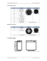
3.3. Sonar Head Pin-Out Diagrams
The following pin out diagrams details the appropriate connectors for each major variant of
the Gemini 720is.
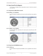
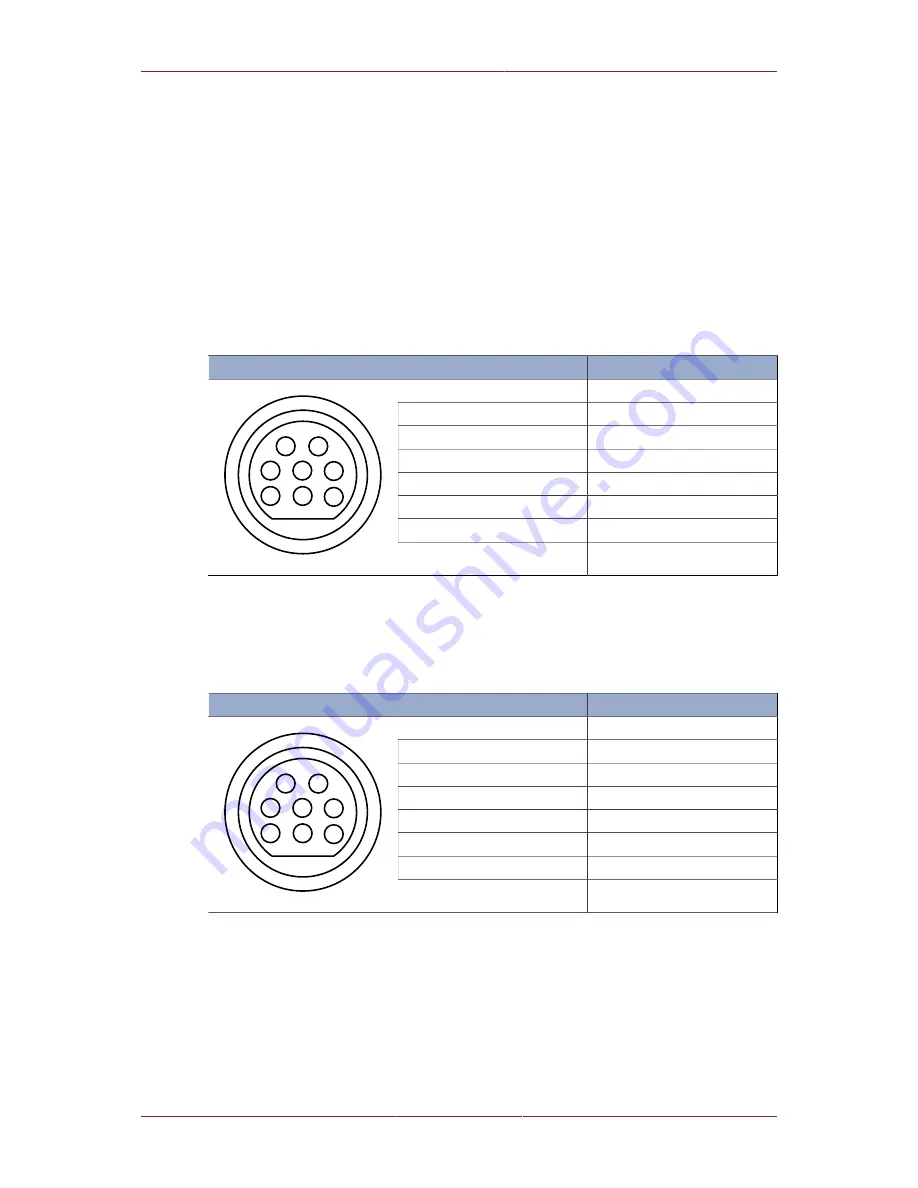
3.3.1. Single Seacon 5506-1508 connector
S11108 (1000m) or S11109 (4000m)
Gemini 720is fitted with a single Seacon 55 series connector using Ethernet communications
only.
Bulkhead view
Pin
Function
1
Ethernet RX+
2
Ethernet RX-
3
Ethernet Tx+
4
DC +
5
N/C
6
Ethernet Tx-
7
DC Ground
5
6
4
1
2
3
7
8
8
N/C
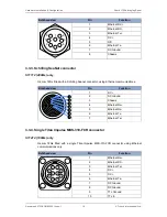
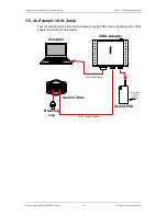
S11110 (1000m) or S11111 (4000m)
Gemini 720is fitted with a single Seacon 55 series connector using Ethernet and VDSL
communications.
Bulkhead view
Pin
Function
1
Ethernet Rx+
2
Ethernet Rx-
3
Ethernet Tx+
4
DC +
5
VDSL +
6
Ethernet Tx-
7
DC Ground
5
6
4
1
2
3
7
8
8
VDSL -
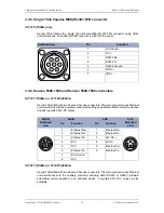
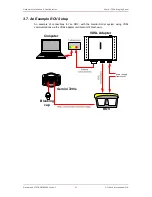
3.3.2. Single Seacon MCBH8M connector
S11107 (1000m) only
Gemini 720is fitted with a single Seacon MCBH8M connector using Ethernet communications
only.


