Gemini Software Operation
Gemini 720is Imaging Sonar
Document: 0703-SOM-00002, Issue: 1
50
© Tritech International Ltd.
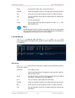
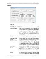
Hz
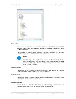
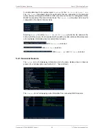
The incoming data rate
String
The incoming data string, check this against the chosen
Decode
if the
data indicator is red.
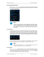
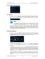
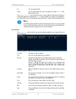
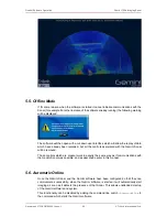
5.3.4. Aux Power
The
Aux Power
will enable, or disable power to the Aux port of the Gemini 720is.
Caution
As the Aux port is powered by an internal regulator, the maximum power limit
should never be exceeding. Doing so will damage the Gemini 720is.
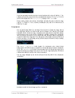
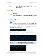
5.4. Multiple Head Operation
Note
The following instructions refer to a Gemini Sonar with a 120° swathe. Other
products within the Gemini range may have differing swathes, but the same basic
principles described apply.
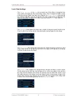
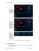
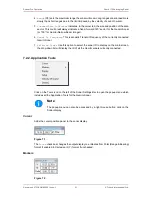
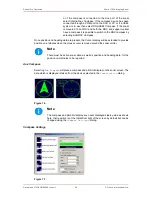
The number of heads connected to a system can be selected using the drop-down list on the
right-hand pane of the
Advanced
screen.
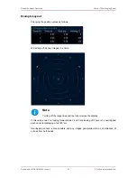
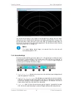
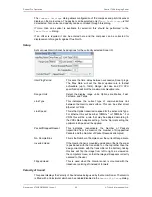
The first time the number of heads is altered the sonar display will place the sonars side-by-
side in a line. Any subsequent alterations to the position or rotation of each sonar image is
stored and recalled when the Gemini software is restarted.
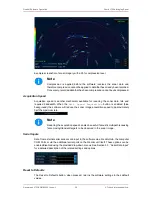
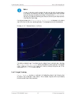
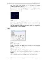
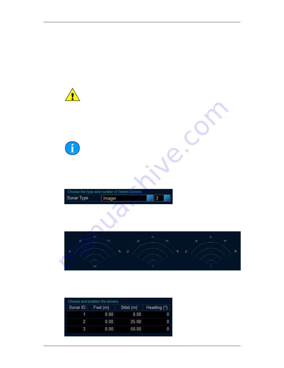
The position of the sonar images can be altered using the text fields listed under
Choose
and position the sonars
. Each text field is editable and allows the sonar scans to be
moved around in relation to a central reference point. The default is as follows:


