background image

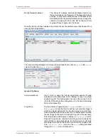
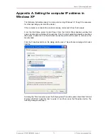
Setting the computer IP address in Windows XP

Gemini 720is Imaging Sonar

Document: 0703-SOM-00002, Issue: 1

72

© Tritech International Ltd.

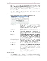
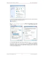
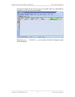
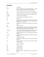
Make a note of the settings as currently used by the computer; these will be needed to restore

the computer to any existing network. Refer to the appropriate section of this manual for the

correct IP address to use.

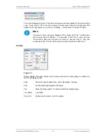
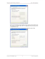
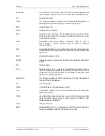
The following screenshot shows the dialog after those changes have been made:

Summary of Contents for 720is

Page 1: ...Gemini 720is Imaging Sonar Document 0703 SOM 00002 Issue 1 1 Tritech International Ltd Gemini 720is Imaging Sonar Product Manual Document 0703 SOM 00002 Issue 1...

Page 2: ...ent is supplied by Tritech International Ltd on the understanding that it may not be copied used or disclosed to others except as authorised in writing by Tritech International Ltd Tritech Internation...

Page 3: ...s 15 3 4 Surface Adapter Pin out Diagrams 16 3 4 1 Ethernet Adapter 16 3 4 2 VDSL Adapter 17 3 5 An Example Ethernet Setup 19 3 6 An Example VDSL Setup 20 3 7 An Example ROV Setup 21 3 8 Multiple Head...

Page 4: ...anet Pro Installation 54 6 1 System requirements 54 6 2 Installing Seanet Pro 54 7 Seanet Pro Operation 57 7 1 Seanet Setup for Gemini 57 7 2 Gemini Sonar Application 59 7 2 1 Sonar Settings 60 7 2 2...

Page 5: ...2 Software or firmware revision numbers 3 A clear fault description 4 Details of any remedial action implemented Contamination If the product has been used in a contaminated or hazardous environment...

Page 6: ...the current topic Important When this is shown there is potential to cause harm to the device due to static discharge The components should not be handled without appropriate protection to prevent suc...

Page 7: ...Housing 4000m version Titanium Housing The Gemini 720is is available with a wide variety of connectors fitted Single Seaconn 5506 1508 Standard option Dual Seaconn 5506 1508 Single Seaconn MC BH 8M Si...

Page 8: ...al Ltd supplied VDSL Adapter Unit takes the two wire VDSL input and bridges it to Ethernet for simple connection to a PC VDSL maximises the data rate by testing the quality of the connection at start...

Page 9: ...supply please refer to Section 2 1 Gemini 720is for more information 1 4 Software Version Note The instructions within this manual apply to the following software versions Gemini software 1 20 00 onw...

Page 10: ...0 5 effective Scanning Sector 120 Number of Beams 256 Vertical Beamwidth 20 tilted down 10 Range 0 2m to 120m Scan Rate 5 30Hz range dependent Range Resolution 8mm range dependent Electrical and Commu...

Page 11: ...clamps should be electrically insulated from the sonar body by either rubber or plastic strips or mounting brackets of at least 3 mm thickness and extending at least 3 mm beyond the clamp boundary to...

Page 12: ...Gemini has two ports then the unused connector must have a blanking cap fitted prior to immersing in water Failure to do this will cause permanent damage If using alcohol or IPA to clean out the conn...

Page 13: ...es connector using Ethernet communications only Bulkhead view Pin Function 1 Ethernet RX 2 Ethernet RX 3 Ethernet Tx 4 DC 5 N C 6 Ethernet Tx 7 DC Ground 5 6 4 1 2 3 7 8 8 N C S11110 1000m or S11111 4...

Page 14: ...ed with a Schilling Seanet connector using Ethernet communications Bulkhead view Pin Function 1 DC 2 DC Ground 3 Chassis 4 Ethernet Rx 5 Ethernet Rx 6 Ethernet Tx 1 2 7 6 5 4 3 7 Ethernet Tx 3 3 4 Sin...

Page 15: ...ted with two Seacon 55 series connectors The main connector uses Ethernet communications with the auxiliary connector providing an additional Ethernet communication line and regulated 24V DC output MA...

Page 16: ...1 2 3 7 8 8 VDSL 6 TTL In 6 5 4 1 2 3 3 4 Surface Adapter Pin out Diagrams Note For all system types the connection to the surface computer or IT infrastructure from the Gemini Hub Ethernet or VDSL ad...

Page 17: ...ernet RX B Ethernet RX C Ethernet TX D DC E DC F Ethernet TX G DC Ground H DC Ground J not connected K not connected L not connected E D C B A J H M K L F G M cable screen Souriau UTS71412S Ethernet D...

Page 18: ...International Ltd Sonar Head Connector Pin Function Diagram Photograph 1 DC Ground 2 DC 3 not connected 4 VDSL 5 VDSL 6 not connected 1 6 2 7 5 3 4 7 cable screen Souriau UTS7147S VDSL DC Connector P...

Page 19: ...1 19 Tritech International Ltd 3 5 An Example Ethernet Setup Test or bench setup for the Gemini Sonar system using Ethernet communications via the Ethernet adapter unit Gemini 720is shown Computer Eth...

Page 20: ...002 Issue 1 20 Tritech International Ltd 3 6 An Example VDSL Setup Test or bench setup for the Gemini Sonar system using VDSL communications via the VDSL adapter unit Gemini 720is shown Computer Gemin...

Page 21: ...00002 Issue 1 21 Tritech International Ltd 3 7 An Example ROV Setup An example of connections for an ROV with the Gemini Sonar system using VDSL communications via the VDSL adapter unit Gemini 720is s...

Page 22: ...Gigabit speeds in order to be able to cope with the data Using the Gemini Hub Available as a separate item from Tritech International Ltd is a Gemini Hub which is capable of powering and communicatin...

Page 23: ...Requirements Minimum Recommended Processor 2GHz 2GHz dual core RAM 1GB 2GB Graphics 3D hardware accelerated graphics card Display 1280x1024 32bit colour 1600x1200 32bit colour Disk space Install is 2...

Page 24: ...cess Firstly the IP address of the computer is set to a value which will communicate with the head The Gemini software is then used to change the IP address of the Gemini The third stage is to reset t...

Page 25: ...he Gemini If the correct changes have been made to the Gemini it should now show as connected in the Gemini software If nothing is displayed check that all values entered were correct and it may be ne...

Page 26: ...creens which are selected by clicking on the tabs at the top left hand of the screen The two screens are the User screen and the Advanced screen The User screen allows the maximum amount of screen to...

Page 27: ...ad When the software is started the head will not be running and the Online button will be grey Clicking the Online button will start the Gemini head the button and the sonar cone image next to it wil...

Page 28: ...include the time when recording started The software has a maximum file size for the logged data files Once this size has been reached the software will stop logging to the current file and open a new...

Page 29: ...t will return to the start of the file and continue Clicking the Repeat button will alternate between the repeat being active and inactive Load Button When the Load button is pressed the software will...

Page 30: ...nn xxx where nnnn is an incrementing index number for the image and xxx is the selected image format For example using a logging directory of C GeminiData the first image captured would be stored in t...

Page 31: ...unted upside down the software has the ability to flip the image from left to right as viewed on the computer screen so that the image still appears correctly oriented to the user The illustration abo...

Page 32: ...are described in more detail in Section 5 2 4 Filter Settings 5 1 12 Sound Velocity Indicator The sound velocity indicator at the upper right hand side of the display shows the sound velocity used by...

Page 33: ...rrows are designed for fine control of the gain and operate one step per click and clicking on the arrows and holding them down will have no effect The gain can also be altered using keyboard shortcut...

Page 34: ...give a measurement between the two points When any measurement has been taken clicking outside the cone will turn the measurement off 5 1 19 Warnings If the Gemini detects that it is not immersed in w...

Page 35: ...onfigurable settings for the software 5 2 1 System Data The first line on the screen gives the versions of the elements which make up the Gemini software and the other lines show status information fr...

Page 36: ...yed by the software The Sonar ID is available on the system data area of the Advanced screen and should be entered in the Sonar box The number of sonars can also be selected up to 4 and each can have...

Page 37: ...ression technique where all sonar data below a determined level is set to zero before compression is applied Increasing the compression level will increase the efficiency of the compression and effect...

Page 38: ...uisition button is enabled blue background the software will reduce the sonar image acquisition speed to approximately half the maximum rate Note Reducing the acquisition speed can also be useful if a...

Page 39: ...ion on the Measurement Tool see Section 5 1 18 Measurements Logging Directories The Primary logging directory selector indicates the write location for all data logging including screenshot captures a...

Page 40: ...stems with insufficient memory If videos are not written correctly or have no frames then decrease the resolution before recording Additionally AVI videos are less memory intensive and may work better...

Page 41: ...er of images received from the sonar It has the effect of removing random noise and rapidly moving targets from the image The Persistence filter retains decreasing amounts of earlier images as well as...

Page 42: ...re 5 2 6 Distance Marker The Distance Marker provides a mechanism for measuring the distance between two points in the Gemini data view This is similar to the Measurement Tool but provides additional...

Page 43: ...istance Marker and Set Point is displayed in the bottom right of the Gemini data view see image below The displayed values are calculated as Distance X Y Distance Marker Set Point The Distance Marker...

Page 44: ...o slow down Active Range Window and Active Bearing Window These settings set up a mask around a tracked target As long as the target moves within the mask from one instance to the next the target will...

Page 45: ...ck on it The highlight box will change colour and the other potential targets will no longer be highlighted The Tracked Targets information will be automatically updated to display the range and beari...

Page 46: ...n list is only for configuration of connected Gemini Hubs Selecting Enabled for either Gemini Hub or COM Ports will alter the tab options in the bottom left of the screen If both are disabled there wi...

Page 47: ...b The Hubs tab shows the status information from any connected Gemini Hubs Hub Setup Tab The Hub Setup tab allows configuration of the serial ports on the rear of the Gemini Hub to allow RS232 data to...

Page 48: ...mplete data string and green is for normal operation 5 3 3 COM Ports The COM Ports enables two extra tabs called Serial Setup and Sonar Ports from where all the serial communication both connected to...

Page 49: ...t is connected Sonar ID The Gemini 720is ID number Port The port or serial channel on the Gemini Decode Changes the intended use for the data being put into the Gemini Decode will enable the selection...

Page 50: ...ar with a 120 swathe Other products within the Gemini range may have differing swathes but the same basic principles described apply The number of heads connected to a system can be selected using the...

Page 51: ...follows Will arrange the sonar images in a circle Note Turning off the range lines and text can improve the display In this case sonar 1 is looking forward while 2 and 3 are looking aft There is no o...

Page 52: ...l the controls associated with the Gemini Sonar will be removed Those controls which are present work in exactly the same way as if communications with the Gemini Sonar was possible and as described e...

Page 53: ...a previous settings file 1 Shut down the Gemini software 2 Delete or rename the C GeminiData Settings Gemini xml file 3 Copy the historical settings xml file into the location C GeminiData Settings an...

Page 54: ...han 160GB recommended for log files Networking 100Mbit s 1 fast Ethernet 1000Mbit s 1 Gigabit Ethernet Software Windows XP 32bit Windows 7 32 or 64bit 6 2 Installing Seanet Pro Seanet Pro is supplied...

Page 55: ...Image Tiler this option installs an additional software package that can mosaic sonar imagery from Seanet Pro onto background images Note Do not attempt to remove the CD ROM from your computer during...

Page 56: ...720is Imaging Sonar Document 0703 SOM 00002 Issue 1 56 Tritech International Ltd Note In order to correctly run the Gemini head on a SCU the SCUv5 or later is required Contact Tritech International Lt...

Page 57: ...Click on Gemini LAN from the Setup menu This will open the Gemini Setup page Gemini Setup Network Enabled Ensure this box is ticked to load the Gemini Connection DLL and start the Gemini Network The...

Page 58: ...pply the in built velocimeter speed of sound calculation to the sonar data Set to Manual to revert to a fixed speed of sound This fixed speed of sound is the manual V O S Velocity Of Sound setting con...

Page 59: ...p down selection being used to confirm the required data rate Data being passed through the Gemini will be automatically decoded by Seanet Pro and displayed in the Gemini application window to the rig...

Page 60: ...ls relate to C1 C3 respectively on a Remote Access Terminal RAT Function buttons F1 F2 will become active whenever a multi device or multi window application is selected from the Applications menu The...

Page 61: ...ic Transmit Frequency of the currently connected Gemini Sonar 7 Selected Sonar Use this option to select the sonar ID to display on the main screen the drop down list will display the ID of all the Ge...

Page 62: ...ay a line will be drawn which connects them The Delta Range and Bearing at the bottom of the panel indicates separation and angle between both Markers There are 4 sets of Markers that can be implement...

Page 63: ...d to be active for the Geo referencing to be functional From USBL Position Updates If a USBL input is active select this option A Heading input will also need to be active for the Geo referencing to b...

Page 64: ...and heading data are present the Cursor display will be extended to provide position co ordinates when the mouse cursor is moved around the sonar plotter Note There must be active sonar data as well a...

Page 65: ...the Gemini and surface This can be either direct Ethernet or VDSL Link Speed This is the Uplink transmission speed for the active Link Type For Ethernet this will be either 10Mbit s 1 or 100Mbit s 1...

Page 66: ...eps of 3 2m s 1 starting from the minimum limit of 1400m s 1 For example if 1402 1m s 1 was set in the Environment page then Gemini will round to nearest 3 2m s 1 step and consequently the Velocity of...

Page 67: ...EMV4 icon on the system tray and double click it to show the main window From the Applications drop down menu select Aux Device Output The Aux Device Output window will now be visible The Port A or Po...

Page 68: ...se Although the Gemini range is not field serviceable regular care and maintenance of the unit should be carried out Ensuring that the electrical connectors are clean and free of corrosion will aid in...

Page 69: ...network administrator for advice if the sonar is connected to a network where disabling the firewall would present a security risk Sonar goes offline while operating on deck The sonar head outputs hea...

Page 70: ...reduce the ping rate slightly but the link will be more reliable in the presence of noise Check all connectors on the VDSL twisted pair poor contacts have been known to cause this issue Ethernet Syst...

Page 71: ...t Menu select Control Panel From the Control Panel Explorer window that opens double click on Network Connections From the list of available network connections that opens double click on the Ethernet...

Page 72: ...ech International Ltd Make a note of the settings as currently used by the computer these will be needed to restore the computer to any existing network Refer to the appropriate section of this manual...

Page 73: ...ws 7 though the sequence for other operating systems will be similar Disconnect the computer from any existing network First click on the Start Menu and select Control Panel Under Network and Internet...

Page 74: ...ialog should be displayed Find the entry labelled Internet Protocol Version 4 TCP IPv4 select it and then click on the Properties button In the properties dialog which opens there will either be Obtai...

Page 75: ...D of the Gemini has been entered at the top of the screen the details for the new IP address can be entered Three items need to be entered the Device ID to ensure that the correct Gemini is being alte...

Page 76: ...sing panel on the right hand side update New IP Address and or New Subnet Mask The text box background colour will change from white to red to indicate a change has been made as shown below Once these...

Page 77: ...03 SOM 00002 Issue 1 77 Tritech International Ltd IP Address for details of how to do this Once communication has been re established the following screen shows the sonar is connected Returning to Gem...

Page 78: ...apable of handling input from various different types of sensors using the following standard strings Depth strings Name Description Format Examples Digi Parascientific Digiquartz depth sensor 000 0 S...

Page 79: ...PR Heading Heave Pitch Roll HEHDT PHTRH OctansHead Heading HEHDT OctansLinear Heading Heave Surge Sway HEHDT PHLIN Octans Std 2 Heading Heave Pitch Roll 00000 0000H 0000 0000F Simard EM3000 Heading He...

Page 80: ...is capable of outputting different data strings depending on the requirement of the user Target tracking strings Name Description Format Examples PTRITAR Basic target tracking output string Gemini 72...

Page 81: ...rking technologies for local area networks LANs GB Gigabyte 1000MB Gemini Unless specified this can refer to any of the multibeam sonars in the Gemini range by Tritech International Ltd such as the Ge...

Page 82: ...ta that have the same value are stored as a single datum point and count ROV Remotely Operated Vehicle RS232 Traditional name for a series of standards for serial binary data control signals RX Receiv...

Reviews: