background image

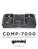
c d m p

-

7 0 0 0


m a n u a l


g e m i n i d j

.

c o m

16

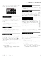
jogwHeeL AdjUST

The JOG ADJUST (7) rotary allows adjustment to 
the feel of the jogwheel. For a stiffer and heavier 
feel, rotate the JOG ADJUST (7) rotary to the 
left. For a looser and lighter feel, rotate the JOG ADJUST 
(7) rotary to the right. 

VinYL mode

Pressing the VINYL (24) button enables VINYL 
mode and illuminates the Vinyl indicator on the 
joghwheel display. 

Enabling VINYL mode allows scratch-like effects when 
the JOGWHEEL (30) is depressed and rotated. When 
VINYL mode is disabled, the JOGWHEEL (30) will be 
in SEARCH MODE and will allow searching through the 
track. 
 
The VINYL button also activates WAH / TRANCE / 
BUBBLE effects set instead of FLTR / FLANGER / ECHO 
set. In this mode rotating the JOG WHEEL will produce 
scratch sound and change the parameters of the effects.

START Time / SToP Time

Adjusting the START TIME (21) jog mode ad-
justment adjusts the speed at which playback 
returns to normal when the top of the jog-
wheel is released and when the unit resumes playback 
from pause mode. The start time increases when turned 
clockwise and decreases when turned counterclockwise. 

The STOP TIME (22) jog mode adjustment adjusts the 
speed at which playback slows when the top of the jog-
wheel is touched and when pause is enabled. The stop  
time increases when turned clockwise and decreases 
when turned counterclockwise. 

SLiP mode

When SLIP (25) is enabled, normal playback con-
tinues inaudibly underneath SCRATCH, LOOP, and 
REVERSE effects. When SCRATCH, LOOP, or REVERSE 
mode is exited, normal playback resumes from the in-
audible playback spot as indicated on the JOGWHEEL 
(30) display.

SLiP wiTH ScRATcH

To use SLIP while scratching, enable VINYL mode by 
pressing the VINYL (24) button. Enable SLIP mode by 
pressing the SLIP (25) button.

Using the jogwheel will now create scratch effects while 
normal track playback continues inaudibly undeneath. 
The position playing underneath is shown on the jog-
wheel display.

Once the jogwheel is released, track playback will con-
tinue from the playback position playing underneath.

NOTE: When using SLIP mode with scratch, SLIP reverse 
operations will not be performed.

SLiP wiTH LooP

To use SLIP with loop playback, enable SLIP mode by 
pressing the SLIP (25) button.

Set a loop (page 12) using the IN/OUT controls and loop 
playback will begin. The SLIP (25) button will begin 
flashing indicating SLIP mode is active and the position 
playing underneath is shown on the jogwheel display.

Upon exiting the loop, track playback will continue from 
the playback position playing underneath. 

SLiP wiTH ReVeRSe

To use SLIP with reverse playback, enable SLIP mode by 
pressing the SLIP (25) button.

Press REVERSE (6) to begin playback in the reverse di-
rection. The SLIP (25) button will begin flashing indicat-
ing SLIP mode is active and the position playing under-
neath is shown on the jogwheel display.

Press REVERSE (6) again to exit reverse playback. Upon 
exiting reverse playback, track playback will continue 
from the playback position playing underneath. 

j o g w h e e l


c o n t r o l s

j o g w h e e l


c o n t r o l s

Summary of Contents for CDMP-7000

Page 1: ...www geminidj com ...

Page 2: ...es Té ch i n as In for maci ón de l a G aran t ía Re gi st ro de l P rodu ct 4 5 7 8 9 10 11 12 15 16 17 18 20 22 24 91 93 48 49 51 52 53 54 55 56 59 60 61 62 64 66 68 91 93 26 27 29 30 31 32 33 34 37 38 39 40 42 44 46 91 93 70 71 73 74 75 76 77 78 81 82 83 84 87 88 90 91 93 français Mises en G arde Introduction Vue d Ensemb le d es Lectures Vue d Ensemb le du Mixer Vue d Ensemb le d es Connexions...

Page 3: ...c d m p 7000 m a n u a l g e m i n i d j c o m 4 ...

Page 4: ... the sound until you can hear it com fortably and clearly and without distortion Once you have established a comfortable sound level set the dial and leave it there Taking a minute to do this now will help to prevent hearing damage or loss in the future After all we want you listening for a lifetime Used wisely your new sound equipment will provide a lifetime of fun and enjoyment Since hearing dam...

Page 5: ...it 44 1 kHz stereo AAC Core AAC Plus AAC Plus v2 AIFF 16 bit 44 1 kHz stereo Supported file systems on Memory Stick Devices include FAT FAT32 HFS NTFS The CDMP 7000 can also send MIDI data from the buttons and dials to a computer to control the parameters and playback controls of DJ software The audio playback from the computer can also be output from the CDMP 7000 Before using the CDMP 7000 as an...

Page 6: ...ot cues Auto cue time Text mode touch on off BPM Lock Lcd touch display Effects Rotary encoder select con trast Back Eject Source select Jog start time Jog stop time Effect dry wet Vinyl Slip mode Range Master tempo Pitch bend Pitch control fader Jogwheel 16 17 18 19 20 21 22 23 24 25 26 27 28 29 30 1 2 3 4 5 6 7 8 9 10 11 12 13 14 15 2 3 4 5 6 7 8 9 10 11 12 13 14 15 16 17 18 19 20 21 22 26 27 28...

Page 7: ...olume Control Headphone Output Switch Cross Fader Start Cross Fader Reverse Cross Fader Cross Fader Curve Adjust Channel Fader 3 Band Channel Equalizer Channel Gain Control Mic Volume Control 2 Band Mic Equalizer Mic Talkover Switch Booth Volume Control t o p v i e w f r o n t v i e w 31 32 33 34 35 36 37 38 39 40 46 41 42 43 44 45 47 48 49 L O 31 31 31 32 33 34 35 36 37 38 39 40 41 42 48 46 49 47...

Page 8: ...ter s audio device select the device on your computer s audio settings RcA Line oUTPUTS The CDMP 7000 contains three different stereo RCA out puts REC MASTER and BOOTH C The MASTER output connects the unit to your main amplifier The RECORD out put can be used to connect the mixer to the record input of a recording unit thus enabling recording of a mix The BOOTH output can be used as an output sour...

Page 9: ...LiBRARY BRowSeR Displays playable tracks and folders TRAcK wAVeFoRm Displays a visual representation the loaded track s audio Pressing the waveform changes the magnification The values are 3 2 seconds 6 5 seconds 12 seconds and 24 seconds TRAcK diSPLAY Simulates a turntable playing at 33 1 3 RPM and displays the current track position cUe PoinT SLiP diSPLAY Displays the CUE point assigned to the t...

Page 10: ...he USB memory device into the USB input E on the top of the CDMP 7000 Upon loading the device the LCD Touch Display will show the folders and tracks on the USB memory device Sd Insert the SD card into the SD card slot F on the top of the CDMP 7000 Upon loading the device the LCD Touch Display will show the folders and tracks on the SD memory device To eject the USB and SD card change the SOURCE SE...

Page 11: ...ocue function When autocue is enabled the player will pause at the beginning of the track Pressing REVERSE 6 will begin playback in the reverse direction Pressing the PITCH BEND 28 will raise the pitch up to 100 or lower the pitch down to 100 from the existing pitch setting Releasing the buttons will return the pitch to the original pitch setting Moving the PITCH CONTROL FADER 29 will accelerate t...

Page 12: ...s restricted to the following 80 196 BPM SeTTing A cUe PoinT While the unit is in playback press PLAY PAUSE ll 2 to pause the track While the track is paused press CUE 3 to set the cue point at the current position The CUE indicator illumi nates when the CUE point is set as well as the marking the CUE point on the Jogwheel display AdjUSTing THe cUe PoinT After the cue point has been programmed pre...

Page 13: ...tarting position for the loop loop in point Press LOOP OUT ADJUST 8 at the desired ending position for the loop loop out position The loop out point is now set and loop playback starts from the loop in point AdjUSTing A LooP To adjust the loop once the loop is set press the OUT ADJUST 8 button The LOOP IN 8 button will stop blinking The length of the loop can be adjusted by rotat ing the jogwheel ...

Page 14: ...e modulation in order to cut the audio s volume in and out e f f e c t s s e c t i o n e f f e c t s c o n t r o l s enABLing An eFFecT During playback the EFFECT 16 section allows you to enable disable effects When VINYL 24 mode is disabled the FLTR FLANGER ECHO effect set are the effects that can be used When VINYL 24 mode is enabled the WAH TRANCE BUBBLE effect set are the effects that can be u...

Page 15: ...y underneath SCRATCH LOOP and REVERSE effects When SCRATCH LOOP or REVERSE mode is exited normal playback resumes from the in audible playback spot as indicated on the JOGWHEEL 30 display SLiP wiTH ScRATcH To use SLIP while scratching enable VINYL mode by pressing the VINYL 24 button Enable SLIP mode by pressing the SLIP 25 button Using the jogwheel will now create scratch effects while normal tra...

Page 16: ...EFFECTS PARAMETER BAR Allows you to set effect values by touching the desired position TRACK WAVEFORM Displays a visual representation the loaded track s audio Pressing the waveform changes the magnification The values are 3 2 seconds 6 5 seconds 12 seconds and 25 seconds TRACK SELECT Allows you to select a track or enter a folder Touching this area will enter a folder AdjUSTing conTRAST Pressing ...

Page 17: ...ID devices This should locate the CDMP 7000 and allow you to use it as a HID device conFigURing midi mode Connect the USB cable from the unit s rear USB port D to the computer Press the MIDI source selection on the CDMP 7000 20 This will terminate playback of the CD USB SD sources The CDMP 7000 will then display an audio configuration prompt for audio bit rate and sampling rate on the touch screen...

Page 18: ...er Parameter Software Parameter Bit Byte Value Cue Cue 1 1 1 on 0 off Play Pause Play Pause 2 1 1 on 0 off pitch bend Pitch 3 1 1 on 0 off pitch bend Pitch 4 1 1 on 0 off HotCue 1 Cue 1 5 1 1 on 0 off HotCue 2 Cue 2 6 1 1 on 0 off HotCue 3 Cue 3 7 1 1 on 0 off Memo Memo 8 1 1 on 0 off Track Search Track reverse 9 1 1 on 0 off Track Seach Track forward 10 1 1 on 0 off Browse Left Up in tracklist 11...

Page 19: ...ER VOLUME 32 control that adjusts the summed output of the 3 channels The VU METER 33 displays the the left and right out put levels of the MASTER OUTPUT NOTE Going above 0dB into the red indicators should be avoided as the signal will distort and could damage other equipment The MASTER BALANCE CONTROL 34 adjusts the L R channel panning on the master output BooTH oUTPUT The CDMP 7000 has a BOOTH V...

Page 20: ...way to the opposite side of the currently playing disc the unit will pause playback of that deck The CROSS FADER REVERSE 40 when enabled inverts the cross fader so that the left side of the cross fader becomes channel 3 and the right of the cross fader be comes channel 2 The CROSS FADER CURVE ADJUST 42 allows for two different cross fader slopes for entering cutting tracks gradual and steep mic co...

Page 21: ...onnecting the USB device to the the unit USB hubs cannot be used with the CDMP 7000 If the unit does not read the USB memory device check to see if the memory device was inserted completely If a Too many devices message appears it is because a USB hub is in use The CDMP 7000 does not work with USB hubs Disconnect the USB hub and connect the USB memory device directly into the CDMP 7000 If a Media ...

Page 22: ...contact diSToRTed oUTPUT If the CDMP 7000 is sending a distorted signal check for the following possible reasons Master output level is too high Input level gain control is too high digiTAL oUTPUT eRRoR If the CDMP 7000 s digital output is not performing check for the following possible reasons The digital output sampling frequency of the CDMP 7000 does not match the specifications of the con nect...

Page 23: ... 20 Hz to 20 kHz PHONO 20 Hz to 20 kHz RIAA 0 5dB MIC 20 Hz to 20 kHz S N ratio at rated output LINE 80dB PHONO 70dB MIC 70dB THD N LINE 0 01 PHONO 0 05 MIC 0 1 Standard input level Input impedance AUX 0dBV 10kΩ PHONO LINE 40dBV 47kΩ 0dBu 1 47kΩ MIC 50dBV 1kΩ balanced Standard output level Minimum Load Impedance MASTER Bal 6 dBv 1kΩ MASTER Unbal 0dBv 1kΩ BOOTH 0dBv 1kΩ REC 0dBv 1kΩ PHONES 200mW 20...

Page 24: ... for any purpose without the express written permission of GCI Technologies Corp It is recommended that all maintenance and service on this product is performed by GCI Technologies Corp or its authorized agents GCI Technologies will not accept liability for loss or damage caused by maintenance or repair performed by unauthorized personnel Worldwide Headquarters 280 Raritan Center Dr Edison NJ 0883...

Reviews: