(6)
14.GND SCREW: Use to reduce the induction of hum or noise by
connecting it to the ground screw of the corresponding instrument of
the rack system.
15.AC SOURCE SELECTOR: Slide this switch to select the AC source,
120V or 230V.
16.FUSE HOLDER: Where the power fuse is located.
17.AC POWER CORD: Insert power cord here.
USING THE GROUND LIFT SWITCH:
Depending on your system configuration, sometimes applying the ground
will create a quieter signal path. Sometimes lifting the ground can
eliminate ground loops and hum to create a quieter signal path.
1. With the unit on, listen to the system in idle mode (no signal present) with
the ground applied (the GROUND LIFT SWITCH (18) in the left position).
2. Then turn the power off before moving the GROUND LIFT SWITCH (18).
Lift the ground by moving the GROUND LIFT SWITCH to the right, turn
the power back on and listen to determine which position will provide a
signal free of background noise and hum. Keep the GROUND LIFT
SWITCH in the ground position if the noise level remains the same in
either position.
CAUTION: DO NOT TERMINATE THE AC GROUND ON THE UNIT IN ANY WAY. TERMINATION OF
THE AC GROUND CAN BE HAZARDOUS.
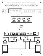
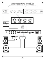
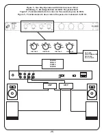
CONNECTIONS AND OPERATION:
Figure 3: Three Way Operation with 180 Hz and 6 kHz Crossover Points
Figure 4: Two Way Operation with 1 kHz Crossover Point
Figure 5: Two Way Operation with 90 Hz Crossover Point
SPECIFICATIONS:
Input Impedance..............................................................................>47K OHM
Crossover Frequency:
LOW..........................................................................50, 90, 180, 360, 720 Hz
MID (HIGH PASS)............................................50, 90, 180, 360, 720 Hz, FLAT
MID (LOW PASS)..............................................1k, 2k, 4k, 6k, 8 kHz and FLAT
HIGH.................................................................................1k, 2k, 4k, 6k, 8 kHz
Filter Slope..................................................................................12 dB/octave
Total Harmonic Distortion.....................................................................<0.01%
Frequency Response (summed).................................20HZ~20KHZ (±0.5dB)
S/N Ratio..................................................................................................90dB
Power Requirement..................................................110V/220V, 50HZ/60HZ
Power Consumption...................................................................................6W
Dimensions....................................19"w x 1.75"h x 8"d (483 x 45 x 203 mm)
INTRODUCTION:
Congratulations on purchasing a GEMINI CX-1000 Electronic Crossover.
This state of the art 3-way active electronic crossover network includes
the latest features and is backed by a three year warranty. Prior to use,
we recommend reading all of the instructions and mailing in the warranty card.
The CX-1000 has four different frequency filter controls and was created to
allow you the flexibility of installing a bi-amp, tri-amp or multi-amp system.
PRECAUTIONS:
Read all operating instructions before using this equipment. To reduce
the risk of electrical shock, do not open the unit. There are
NO USER REPLACEABLE PARTS INSIDE. Please contact the Gemini
Service Department or your authorized dealer to speak to a qualified
service technician. Be sure that all AC power is OFF while making
connections. Cables should be low capacitance, shielded and of proper
length. Make sure that all plugs and jacks are tight and properly
connected. Always begin with the audio level faders/volume controls
set at minimum and the speaker volume control(s) set to OFF. Wait 8 to
10 seconds prior to turning up the speaker volume to prevent the
transient “POP” that could result in speaker/crossover damage. We
recommend setting the power amplifiers’ volume controls to maximum
(highest sensitivity) and then set the crossover’s volume controls to the
necessary level for proper operation of the complete system (starting
from zero and going up). DO NOT EXPOSE THIS UNIT TO RAIN OR
MOISTURE. DO NOT USE ANY SPRAY CLEANER OR LUBRICANT ON
ANY CONTROLS OR SWITCHES.
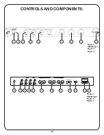
CONTROLS AND COMPONENTS
(FRONT) - FIGURE 1:
1. POWER ON/OFF SWITCH: Use to turn unit ON or OFF.
2. POWER ON LED INDICATOR: Lights up when unit is on.
3. LOW FREQUENCY CROSSOVER SWITCH: Use to select the crossover
frequency point between low and mid-range at 50, 90, 180, 360, 720 Hz.
4. MID FREQUENCY CROSSOVER HIGH-PASS FILTER SWITCH: Use to
select the low frequency crossover point of the high-pass filter of mid-
range at 50, 90, 180, 360, 720 Hz or to set it FLAT.
5. MID FREQUENCY CROSSOVER LOW-PASS FILTER SWITCH: Use to
select the high frequency crossover point of the low-pass filter of mid-
range at 1k, 2k, 4k, 6k, 8 kHz or to set it FLAT.
6. HIGH FREQUENCY CROSSOVER SWITCH: Use to select the crossover
frequency point between high and mid-range at 1k, 2k, 4k, 6k, 8 kHz.
7. LOW FREQUENCY LEVEL (VOLUME) CONTROL: Use to adjust the
output level of low frequency output.
8. MID FREQUENCY LEVEL (VOLUME) CONTROL: Use to adjust the
output level of mid frequency output.
9. HIGH FREQUENCY LEVEL (VOLUME) CONTROL: Use to adjust the
output level of high frequency output.
CONTROLS AND COMPONENTS
(REAR) - FIGURE 2:
10.INPUT CONNECTOR (left and right): Use the RCA jacks to connect to
the PRE-AMP output.
11.HIGH FREQUENCY OUTPUT CONNECTOR (left and right): Use the
RCA or XLR jacks to connect to the power amplifier for high frequencies.
12.MID FREQUENCY OUTPUT CONNECTOR (left and right): Use the
RCA or XLR jacks to connect to the power amplifier for mid frequencies.
13.LOW FREQUENCY OUTPUT CONNECTOR (left and right): Use the
RCA or XLR jacks to connect to the power amplifier for low frequencies.
In the U.S.A., if you have any problems with this unit, call
1-732-738-9003 for customer service. Do not return equipment
to your dealer.


