!
ATTENTION
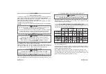
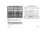
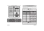
Nominal supply voltage
Nominal supply voltage range
Current absorption @ 12Vdc in stand-by
Operating temperature range
Engine block contact rating
12/24 Vdc
9 to 32
Less than
mA
-20°C to +70°C
8A @ 20°C
10
Vdc
17.0 - TECHNICAL SPECIFICATIONS
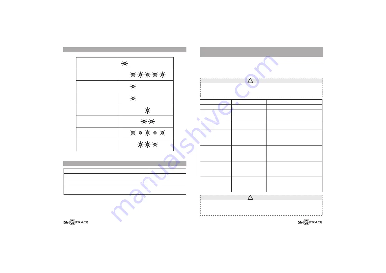
18.0 -
CONFIGURATION
(YELLOW/GREEN wire)
The auxiliary negative input
According to the required connection
.
AUXILIARY INPUT
allows for many connections and configurations.
, program the input (by sending an SMS)
as indicated in the table below
aux#password#0
aux#password#1
aux#password#2
aux#password#3
aux#password#4
aux#password#5
aux#password#6
aux#password#7
Input active 24/7
Input only active
when system is armed
Input active 24/7
Input only active
when system is armed
System activation
System activation
System activation
System activation
Negative
Negative
Positive (lack of negative)
Positive (lack of negative)
Negative pulse activates the
system (60” arming delay),
negative pulse deactivates the
system
Positive pulse activates the system
(60” arming delay), positive pulse
deactivates the system
Continuous negative presence
actives the system (60” arming
delay), lack of negative deactivates
the system
Continuous lack of negative
activates the system (60” arming
delay), continuous negative
presence deactivates the system
COMMAND
ACTIVATION
SIGNAL
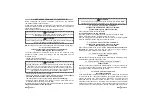
Sending commands
and
will program
the system to forward an alarm message in case of ignition detection
(arming message must have been priorly sent, see par. 5.11 and 8.0.
aux#password#1
aux#password#3
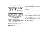
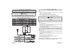
16.0 - OPTICAL SIGNALS
System armed
LED steady ON for
max 20
”
Every 5/7 seconds
LED will flash for
approx. 30
”
System
configuration OK
System arming
System disarming
Weak GSM field (when
engine is turned off)
Satellite reception
indication
(with +15/54)
Satellite search
(with +15/54)
System initializing
!
ATTENTION
The system is configured with the YELLOW/GREEN wire active 24/7,
negative input enabled to send generic alarm SMS to the 1st preset
number.