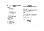
CONTENTS
USER MANUAL
INSTALLER MANUAL
1.0
2.0
3.0
4.0
5.0
7.0
8.0
10.0
11.0
12.0
13.0
14.0
15
17.0
-
- OPERATION
-
larm (
-
- MESSAGE
-
-
WASTE ELECTRICAL AND ELECTRONIC EQUIPMENT (WEEE)
DIRECTIVE
-
- SIM CARD
-
-
-
OPTICAL
-
GENERAL ADVICE
ALARMS
3.1 - Displacement alarm
3.2 - Ignition detection alarm
3.3 - Battery tamper alarm
3.4 - Generic a
yellow-green wire)
S FROM AND TO THE SYSTEM
5.1 - Initial configuration
5.2 - STOP & GO activation command
5.3 - STOP & GO deactivation command
5.4 - Vehicle localization command
5.5 - Tracking command (vehicle movement)
5.6 - Speed control command
5.7 - Engine stop activation command
5.8 - Engine stop deactivation command
SIM validity check command (frequency)
5.10 - Periodic position control command
5.11 - System arming command
5.12 - System disarming command
5.13 - System status request command
5.14 - A
- EXAMPLE OF MyGTRACK MANAGEMENT
6.1 - System configuration
6.2 - Vehicle localization
VEHICLE PARKING
MESSAGE OVERVIEW
-
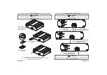
GENERAL INSTALLATION ADVICE
ANTENNA CONNECTIONS
ELECTRICAL CONNECTIONS
SYSTEM CONFIGURATION
- CONTROL UNIT INSTALLATION AND MAINTENANCE
-
SIGNALS
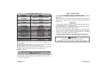
TECHNICAL SPECIFICATIONS
- AUXILIARY INPUT CONFIGURATION
6.0
9.0
.0
16.0
18.0
SUMMARY TABLE OF ALARM MESSAGES
5.9 -
uxiliary input configuration command
UK
1.0 - GENERAL ADVICE
2.0 - OPERATION
Keep note of your Password as you will need it to communicate with
the system.
Dear Customer,
(par. 8.0).
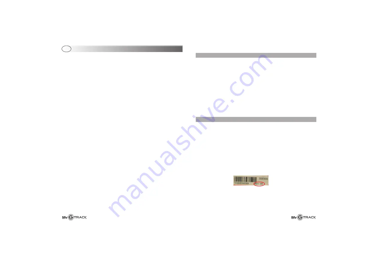
NB: The
is only applicable to devices labeled as follows:
Google Maps link
thank you for purchasing this self-managed MyGTRACK GPS sytem designed
and manufactured in Italy by GEMINI Technologies.
Please read the present manual carefully to fully take advantage of all the
security features offered by the system and avoid triggering false alarms which
use up your SIM credit.
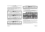
If the MyGTRACK is set up with a prepaid SIM card, periodically check on your
balance to make sure you always have enough credit and use the “validity
check” automatic feature (see message chapter).
In case of theft, you can receive an SMS message with the vehicle current
position and immobilize the engine by sending an SMS to the system.
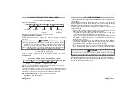
Moreover, by connecting the YELLOW-GREEN wire (negative signal in alarm,
par. 18.0), the system will send an ALARM message to the first preset number.
See the message overview table for the available functions and system
arming/disarming modes
• 7892
=> Rev.10 and higher.
• 7892
=> Rev. 05 and higher.
My01
My11
USER MANUAL