background image

!

ATTENTION

!

ATTENTION

3.0 - ALARMS

3.1 - DISPLACEMENT ALARM

system disarmed

The system

(

) and the

.

.

The

provides protection against possible displacement attempts of the

vehicle when ignition is turned off ex. towing
When ignition is switched back

ON

, the system compares the current

position with the position recorded upon last switch-off
If they differ (value above the factory set, unalterable, tolerance), the system
will send the user an alarm message.

P.P.C. function (par. 5.10) allows tracking vehicle position while the system

is armed.

Transmission of a generic alarm message is subject to connection of the

dedicated wire and system configuration by the installer.

This alarm is only triggered if the

system arming

command

on#password#

(

aux#password#n

has been previously sent par. 5.11 or 8.0) or if the

system has been armed via the

command

(par 5.14 or 8.0).

When the message is sent, the system checks the alarm source. If still active, it
will be inhibited (i.e. door still open). If not active (i.e. door closed), it will be
restored to guarantee protection again.

3.2 - IGNITION DETECTION ALARM

The
alarm will be triggered and an alarm message will be sent if power supply is cut-off

system rovides protection against power source and wiring tampering. An

.

p

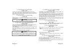
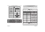
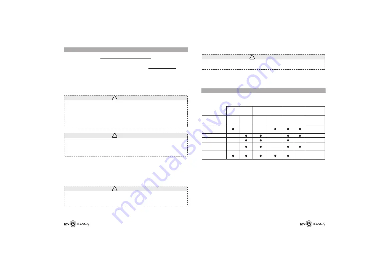
4.0 - SUMMARY TABLE OF ALARM MESSAGES

In case of an alarm condition, the system sends a text message to the user
indicating the type of alarm (see table below).

*

Periodic Position Control.

Ignition detection, displacement (P.P.C.) and power cut-off alarms are subject
to tracker activation via SMS message or configuration of auxiliary input for
system arming via an external module.

The available configurations of the auxiliary input are detailed in par. 18.0.

All text messages provide vehicle position coordinates, speed, date and time.

An

over speed alarm

can also be forwarded to the 1st number only, when the

system is disarmed and ignition key is ON (par. 5.6).

Position

(last stop)

Start

Power cut

Position

(PPC*)

Alarm

(AUX input= 0)

3.1

3.2

3.3

5.10 and

8.0

3.4, 5.14

and 18.0

ON

OFF

IGNITION KEY

SYSTEM

STATUS

ARMED

DISARMED

1

st

number

PHONE

2

nd

number

PAR.

REF.

ALARM

3.4 - GENERIC

yellow-green wire)

ALARM (connection of

!

ATTENTION

The

last valid position

is the vehicle last recorded position (lat., long.,

time and date) when ignition key is turned OFF.

The recorded position remains unvaried until ignition is turned back ON or

in case of an alarm or if the

periodic position control

command is

activated (the last two conditions are only available if the system is

armed).

If someone breaks in the vehicle while the system is armed and attempts to
turn ignition ON

sends an alarm message.

After the message is sent to the 1st preset number, the system checks the
alarm source. If still active, it will be inhibited (ex. ignition key

ON

). If not active

(ex. ignition key

OFF

) it wil be restored to guarantee protection again.

, the system

3.3 - BATTERY TAMPER ALARM

!

ATTENTION

This alarm is only triggered if the

system arming

command

on#password#

aux#password#n

has been previously sent (par. 5.11 or 8.0) or if the system

has been armed via the

command (par 5.14 or 8.0).

Summary of Contents for MyGTRACK 7892 MyMINI

Page 1: ...ture INSTALLATION CERTIFICATE The undersigned qualified installer attests having personally fitted the GPS system on the vehicle specified below following the manufacturer s instructions GEMINI Technologies S r l Via Luigi Galvani 12 21020 Bodio Lomnago VA Italia Tel 39 0332 943211 Fax 39 0332 948080 www gemini alarm com ISO 9001 Certified Company ...

Page 2: ...S AUXILIARY INPUT CONFIGURATION 6 0 9 0 0 16 0 18 0 SUMMARY TABLE OF ALARM MESSAGES 5 9 uxiliary input configuration command UK 1 0 GENERAL ADVICE 2 0 OPERATION Keep note of your Password as you will need it to communicate with the system Dear Customer par 8 0 NB The is only applicable to devices labeled as follows Google Maps link thank you for purchasing this self managed MyGTRACK GPS sytem desi...

Page 3: ...tection displacement P P C and power cut off alarms are subject to tracker activation via SMS message or configuration of auxiliary input for system arming via an external module The available configurations of the auxiliary input are detailed in par 18 0 All text messages provide vehicle position coordinates speed date and time An over speed alarm can also be forwarded to the 1st number only when...

Page 4: ...onal country code 44 for UK 6 digit code mandatory setup ok with password new password ATTENTION The system can be configured with the STOP GO feature SMS message when ignition is turned ON or OFF see par 5 2 5 3 or 8 0 5 2 STOP GO ACTIVATION COMMAND 5 3 STOP GO DEACTIVATION COMMAND 5 4 VEHICLE LOCALIZATION COMMAND 5 5 TRACKING COMMAND VEHICLE MOVEMENT setup password can main phone number new pass...

Page 5: ...est the system will arm and send the user a confirmation message System armed GPS ok latitude longitude speed time date Upon request the system will disarm and send the user a confirmation message System disarmed GPS status latitude longitude speed time date Upon request the system will reply System status armed or disarmed GPS status latitude longitude speed time date 5 9 pol password 045 Code 04...

Page 6: ...icable to devices labeled Rev 10 and higher Rev 05 and higher NB GoogleMaps link NB My01 My11 7892 7892 7 0 VEHICLE PARKING Sometimes covered parking structures obstruct reception of GPS signals which makes it impossible to get a location fix the system will nonetheless register the last visible position before entering the parking red parking structures if not multi floor underground garage have ...

Page 7: ...ord 045 pos password 180 on password off password status password aux password n ref 01 ref 02 ref 03 ref 04 COMMAND 10 0 GENERAL INSTALLATION ADVICE Dear installer MyGTRACK systems are safety devices that provide full active protection to 12 24V vehicles via GPS location tracking and GSM communication by mobile phone IMPORTANT The GSM antenna must be installed in a well hidden but easily accessib...

Page 8: ...UT THE SIM CARD TRAY INSERT THE SIM IN THE TRAY REPLACE THE TRAY MAKING SURE THAT THE SIM LABEL ON THE TRAY IS ALIGNED WITH THE SIM CARD MARKING ON THE UNIT GSM ANTENNA RECEPTION TRANSMISSION BY GSM NETWORK The control unit MUST be POWERED OFF when you carry out the following operations ATTENTION The control unit MUST be POWERED OFF when you carry out the following operations ATTENTION During inst...

Page 9: ...approx 1 minute to get valid GPS data 15A ATTENTION If you are unsure whether the first initialization has been done correctly repeat the operation by disconnecting the module and reconnecting it after a few minutes 15 0 MyGTRACK systems are electronic devices which require suitable installation and maintenance Fit the module in a horizontal position respect to the vehicle axis in a well hidden po...

Page 10: ...ative pulse activates the system 60 arming delay negative pulse deactivates the system Positive pulse activates the system 60 arming delay positive pulse deactivates the system Continuous negative presence actives the system 60 arming delay lack of negative deactivates the system Continuous lack of negative activates the system 60 arming delay continuous negative presence deactivates the system CO...

Reviews: